Shielding Effectiveness test Set-Up Guide.
Shielding Effectiveness test Set-Up Guide.
The article will address the shielding effectiveness testing process. No matter the standard for shielding effectiveness, the general procedure for testing shielding compliance follows the same process.
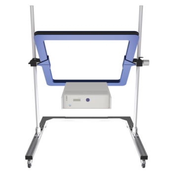
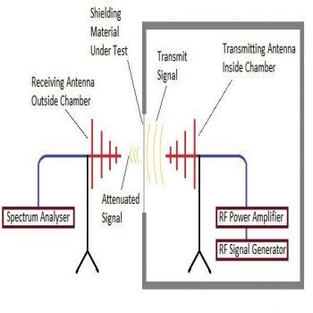
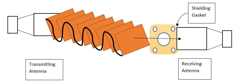
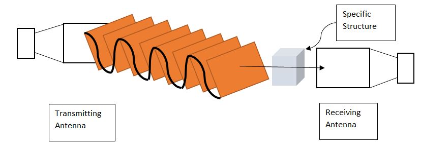
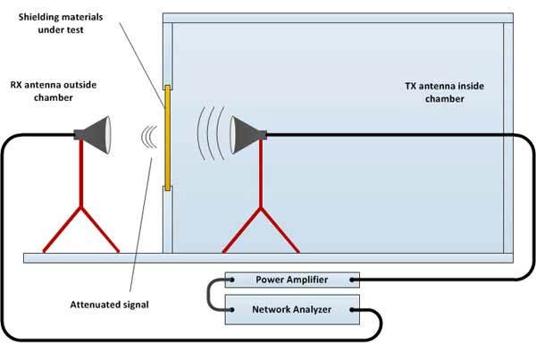
First, two antennas are set up on opposite sides of the sample for the test. One antenna acts as a transmit antenna. It is connected to a signal generator to sweep through the required frequency range. The second antenna is a receive antenna. This antenna measures the received field strength. This information is stored in data form. The data represents the signal attenuation or loss of signal through the barrier.

As verification of results, there is a prior step to the actual measurement of the sample under test. This step requires a calculation of the dynamic range such that accurate results are being made. Therefore, two measurements must be made.
- The first is with no barrier. This means there is nothing between the transmitting and receiving antenna.
- The second measurement is with a barrier. This is typically a metallic surface that is the best under materials used in shielding. The resulting signal should be the floor-level noise of the antenna and receiver with an additional safety margin. This is usually 6 dB, to take into account for error.
- Once these two verification measurements are taken, the dynamic range can be calculated.
- This is simply the difference between the maximum and minimum signals.
The amount of dynamic range must be greater than the amount of desired signal attenuation from the enclosure shielding. Otherwise, the unit outperforms the test chamber and thus concludes the sample shields better than the chamber, which should never be the case. It is important to always verify the data, especially if the outcome appears to support this situation.
There are two kinds of measurements that can be taken regarding an electric or magnetic field.
The first is a far-field electromagnetic wave. The second is a near-field electromagnetic field. When considering a far-field electromagnetic wave measurement, this is when the electric and magnetic fields are orthogonal or perpendicular to each other. The normal, or along with, is the direction of the energy generation. In the test setup, this would be the signal generator. For the opposite direction, this is just the opposite case. This is where there is no region where the electric and magnetic fields are related at all. In other words, considering the working of an antenna system, the near field is very close to the antenna, and far-field means further away.
In addition to determining the shielding of materials, we can also access the shielding of cables. The shielding of cables can reduce the coupling of radio waves, electromagnetic fields, and electrostatic fields. The amount of reduction can vary based on several factors. For instance, the material used, its thickness, the size of the shielded volume, and the frequency of the fields of interest can all have an impact. Also impacting the effectiveness of the shielding is the size, shape, and orientation of apertures in a shield to an incident electromagnetic field. Do not forget the perfect connection of the frame to the sample under test! It is required to be better than the screen level of the sample to avoid leakage and false measurements. To ensure a perfect connection could be necessary to apply on the border: silver paint, silver silicon glue, silver-metal PU glue, fingers strips, copper adhesive tape, aluminum tape and to end a bit of experience!…
LIMITS of Application
Due to the difficulties to have a repeatable test condition (maintain a faraway field wave propagation) this test method is generally applied from 0,7 to 40GHz by mean of broadband horn antennas
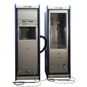
Instruments required for a full coverage 10KHz-18GHz (optional expansion to 40 GHz)
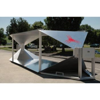
- Primary is necessary a shielded box at least 1m3. Volume lined with absorbers with a couple of ridge horn antennas according to the different frequency band (700MHz-18GHz)
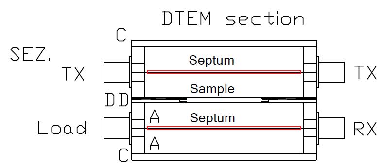
- A double TEM cell coupled to cover low frequencies from DC to 3GHz
- RF signal or sweep generators (10KHz-20GHz)
- Receiver (or spectrum analyzer 9KHz-26GHz)
- Amplifiers (more than 1 depending on the frequency range up to 4-5W)
- Pre-Amplifiers (broadband 10KHz-20GHz 15dB)
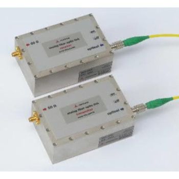
- Coaxial cables (low loss, high quality!)
- Fixed attenuators 10-20-20-30dB
- Adaptors Kit N to SMA connectors
Reference Standards
Many are the standards about the Shielding Effectiveness, each one is specific for the kind and shape of materials, and frequency range. Here is an overview:
ASTM F3057-14 -Measuring the Effectiveness of Electromagnetic Shielding of Glazing/Glasses
It is a new and the best method that focuses on glazings/glasses or glazing configurations at a specified full-range frequency from 100kHz to 20 GHz and covers the determination of the electromagnetic shielding effectiveness. This is a component test. It is not applicable to full systems such as walls, floors, ceilings, shielded racks, or window systems and it is used to standardize a measurement procedure for glazings or glazing configurations, with and without coatings, films, interlayers, or other enhancements, as single or insulating units at a standard size and when mounted in a standardized frame.
ASTM D 4935-10: -Standard Test Method for Measuring the Electromagnetic Shielding Effectiveness of Planar Materials
The ASTM D 4935-10 standard involves the measurement of shielding effectiveness of planar material (square) for plane far-field Electromagnetic waves. The samples under test must be electrically thin for a near field magnetic field (H) calculation. Electric field shielding effectiveness can be calculated for far-field as well, but applicability has yet to be established. Measurements are to be taken within a frequency range of 30 MHz – 1.5GHz.
ASTM D4935-18: -Measuring the Electromagnetic Shielding Effectiveness of Planar Materials
The Standard ASTM D4935-18 describes how measuring the electromagnetic (EM) shielding effectiveness (SE) of a planar material for a plane, far-field EM wave. The measurement method is valid over a frequency range of 30 MHz to 1.5 GHz. These limits are not exact but are based on decreasing displacement current as a result of decreased capacitive coupling at lower frequencies and on overriding (excitation of modes other than the transverse electromagnetic mode (TEM)) at higher frequencies for the size of specimen holder described in this test method. This test method is not applicable to cables or connectors.
ASTM D 4935-99: Standard Test Method for Measuring the Electromagnetic Shielding Effectiveness of Planar Materials
The ASTM D 4935-99 standard involves the measurement of shielding effectiveness of planar material (square) for plane far-field Electromagnetic wave. The samples under test must be electrically thin for a near field magnetic field (H) calculation. Electric field shielding effectiveness can be calculated for far-field as well, but applicability has yet to be established. Measurements are to be taken within a frequency range of 30 MHz – 1.5GHz and follows the typical setup of shielding effectiveness.
IEEE 299-2006: Measuring The Effectiveness Of Electromagnetic Shielding Enclosures
It defines the uniform measurement procedures and techniques for determining the effectiveness of electromagnetic shielding enclosures, It defines the uniform measurement procedures and techniques for determining the effectiveness of electromagnetic shielding enclosures at frequencies from 9 kHz to 18 GHz (extendable to 50 Hz and 100 GHz, respectively) for enclosures having all dimensions greater than or equal to 2 meters. The types of enclosures covered include, but are not limited to, single-shield or double-shield structures of various construction, such as bolted demountable, welded, or integral with a building; and made of materials such as steel plate, copper or aluminum sheet, screening, hardware cloth, metal foil, or shielding fabrics.
It can be any classification of the enclosure but must serve a purpose to shield from exterior electric or magnetic fields, or in a similar fashion, protect the environment around itself from the effect of an interior electric or magnetic field.
MIL-DTL-83528C: General Specification For Gasketing Material, Conducting Shielding Gasket, Electronic, Elastomer, EMI / RFI
The MIL-DTL-83528C standard involves the measurement of shielding effectiveness of gasketing material, specifically of elastomeric shielding gaskets. The following material of which these gaskets are made of type qualifies under this standard:
- Silver-plated copper-filled silicone rated for shielding effectiveness of a 110-dB plane wave at 10 GHz
- Silver-plated aluminum-filled silicone rated for shielding effectiveness of a 110-dB plane wave at 10 GHz
- Silver-plated copper-filled flurosilicone rated for shielding effectiveness of a 110-dB plane wave at 10 GHz
- Silver-plated aluminum-filled silicone rated for shielding effectiveness of a 90-dB plane wave at 10 GHz
- Medium pure silver-filled silicone durometer rated for shielding effectiveness of a 110-dB plane wave at 10 GHz
- Pure silver-filled flurosilicone rated for shielding effectiveness of a 110-dB plane wave at 10 GHz
- Silver-plated copper-filled silicone rated for shielding effectiveness of a 110-dB plane wave at 10 GHz
- Pure silver-filled high durometer silicone rated for shielding effectiveness of a 110-dB plane wave at 10 GHz
- Pure silver-filled low durometer silicone rated for shielding effectiveness of an 80-dB plane wave at 10 GHz
- Copper-filled silver-plated high durometer rated for shielding effectiveness of a 110-dB plane wave at 10 GHz
- Nickel-filled silver-plated silicone rated for shielding effectiveness of a 100-dB plane wave at 10 GHz
- Glass-filled silver-plated silicone rated for shielding effectiveness of a 100-dB plane wave at 10 GHz
Measurements are made using the plane wave shielding effectiveness method. The gasket will be determined by its ability to electrically bond a test cover panel to an enclosure flange so the radiated RF plane wave will attenuate through a 24-by-24-inch opening. The enclosure needs to be large enough so no part of the transmitting antenna is within one meter of any enclosure surface.
MIL-G-83528B: General Specification for Gasketing Material, Conducting Shielding Gasket Electronic, Elastomer, EMI / RFI
This standard precedes the MIL-DTL-83528B standard.
The MIL-DTL-83528C standard involves the measurement of shielding effectiveness of gasketing material, specifically of elastomeric shielding gaskets. The following material of which these gaskets are made of type qualifies under this standard:
- Silver-plated copper-filled silicone rated for shielding effectiveness of a 110-dB plane wave at 10 GHz
- Silver-plated aluminum-filled silicone rated for shielding effectiveness of a 110-dB plane wave at 10 GHz
- Silver-plated copper-filled flurosilicone rated for shielding effectiveness of a 110-dB plane wave at 10 GHz
- Silver-plated aluminum-filled silicone rated for shielding effectiveness of a 90-dB plane wave at 10 GHz
- Medium pure silver-filled silicone durometer rated for shielding effectiveness of a 110-dB plane wave at 10 GHz
- Pure silver-filled flurosilicone rated for shielding effectiveness of a 110-dB plane wave at 10 GHz
- Silver-plated copper-filled silicone rated for shielding effectiveness of a 110-dB plane wave at 10 GHz
- Pure silver-filled high durometer silicone rated for shielding effectiveness of a 110-dB plane wave at 10 GHz
- Pure silver-filled low durometer silicone rated for shielding effectiveness of an 80-dB plane wave at 10 GHz
- Copper-filled silver-plated high durometer rated for shielding effectiveness of a 110-dB plane wave at 10 GHz
- Nickel-filled silver-plated silicone rated for shielding effectiveness of a 100-dB plane wave at 10 GHz
- Glass-filled silver-plated silicone rated for shielding effectiveness of a 100-dB plane wave at 10 GHz
Measurements are made using the plane wave shielding effectiveness method. The gasket will be determined by its ability to electrically bond a test cover panel to an enclosure flange so the radiated RF plane wave will attenuate through a 24-by-24-inch opening. The enclosure needs to be large enough so no part of the transmitting antenna is within one meter of any enclosure surface.
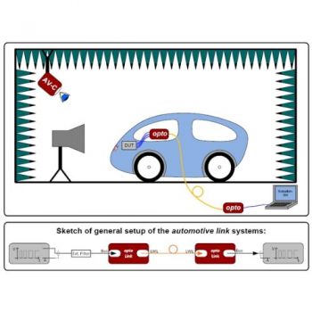
MIL-STD 1377: Measurement And Effectiveness Of Cable, Connector, And Weapon Enclosure Shielding And Filters In Precluding Hazards Of Electromagnetic Radiation To Ordnance
The MIL-STD-1377 specification is specifically for a weapon developer or designer with shielding effectiveness test methods. The actual methods of the shielding effectiveness test are for weapon enclosures, cables, and cable connectors. The weapon enclosure can involve an enclosure that surrounds the weapon circuit, the cable is wiring that starts outside of the enclosure and enters inside and is connected to circuits inside the weapon enclosure, and cable connectors are simply what connects everything together for the overall system. The test is performed over a frequency range of 100 kilohertz (kHz) up to 30 megahertz (MHz), then from 1 gigahertz (GHz) to 10 gigahertz (GHz).
As depicted in the figure, the test setup is the same as other shielding effectiveness, with the determination of the dynamic range and the actual measurement of the signal for the sample in question. If the system involves a weapon enclosure, all internal components need to be removed such that only the enclosure is being tested.
MIL-STD-188-125-1: High-Altitude Electromagnetic Pulse (HEMP) Protection For Ground-Based C4I Facilities Performing Critical, Time-Urgent Missions (Transportable Systems)
MIL-STD 188-125-1 details the minimum performance requirements for low-risk protection from mission-aborting damage due to HEMP attacks. The description of these threats are defined in MIL-STD-2169. MIL-STD-188-125-1 also addresses minimum testing requirements for demonstrating that prescribed performance has been achieved and for verifying that the installed protection subsystem provides the operationally required hardness for the completed facility.
The MIL-STD-188-125-1 test specification defines the design and testing criteria for specifically designated fixed ground-based facilities in HEMP-hardened, critical, time-urgent C4I networks. Facilities include subscriber terminals and data processing centers, transmitting and receiving communications stations, and relay facilities. MIL-STD-188-125-1 applies to both new construction and the retrofit of existing facilities.
Although only local portions of facility interconnects are addressed, it is assumed that survivable long-haul communications paths, fiber optic links, or other hardened interconnects between facilities will be provided as required for mission accomplishment. MIL-STD-188-125-1 can also be used for HEMP protection of other ground-based communications-electronics facilities that require HEMP hardening.
MIL-STD-188-125-2: High-Altitude Electromagnetic Pulse (HEMP) Protection For Ground-Based C4I Facilities Performing Critical, Time-Urgent Missions (Transportable Systems)
The MIL-STD-188-125-2 standard creates the requirements and objectives for design regarding a system's ability to comply with a high-altitude electromagnetic pulse (abbr. HEMP) hardening (resistive) of transportable ground-based systems with features of time-urgent command, control, communications, computer, and intelligence (abbr. C4I) missions. Specifically, this is a series with a companion specification of MIL-STD-188-125-1, with the only difference that this specification, addresses only transportable systems, whereas MIL-STD-188-125-1 addresses fixed facilities. In other words, this addresses the minimum requirements for showing a predetermined performance has been achieved and for verifying installed protection measures provide operationally required HEMP for the completed system.
system examples include, and are not limited to, subscriber terminals and data processing centers, transmitting and receiving communications stations, and relay systems under the assumption that long-haul communications paths, fiber optic links, or other hardened interconnects between systems are provided as required as such in the field. These are specifically itemized out in the specification under Section 5: Detailed Requirements. These relate to transportable systems such as electrical shielding enclosures or fixed rooms in buildings (or the building itself), as long as the unit fulfills the sole purpose of the specification: the owner will determine if the observed event is mission aborting (passing criteria).
The test setup is the same as other shielding effectiveness, with the determination of the dynamic range and the actual measurement of the signal for the sample in question. If the system involves a weapon enclosure, all internal components need to be removed such that only the enclosure is being tested.
MIL-STD-285: Military Standard For Attenuation Measurements For Enclosures.
The MIL-STD-285 standard actually replaced by IEEE-299. describes uniform procedures for measuring SE for enclosures at frequencies from 9 kHz to 18 GHz (extendable down to 50 Hz and up to 100 GHz), although the smallest linear dimension of the enclosure is assumed to be at least 2 m; the selection of 2 m as the smallest linear dimension was originally based upon being able to fit a typical bicone-style antenna inside an enclosure to perform plane-wave testing down to the range from 30 to 50 MHz. The standard does not give any limits for pass/fail, leaving to the owner of the shielding enclosure to provide these limits. In addition, although the standard suggests a range of test frequencies that can provide confidence in the effectiveness of the shield, it is clearly stated that the actual test frequencies must be chosen according to a test plan approved by the shield owner, the tester, and the shielding provider/vendor. The measurement range in this method is divided into three subranges and in each subregion, some subgroups of testing frequencies are suggested:
- A low-frequency range, from 9 kHz (50 Hz) to 20 MHz (a single frequency is suggested within 9–16 kHz, 140–160 kHz, and 14–16 MHz) where the SE is defined in terms of magnetic-field performance.
- A resonant range, from 20 to 300 MHz, where the SE is expressed in terms of either electric field or power.
- A high-frequency range from 300 MHz to 18 GHz (100 GHz) (a single frequency is suggested within 300–600 MHz, 600–1000 MHz, 1–2 GHz, 2–4 GHz, 4–8 GHz, and 8–18 GHz) where the shielding performance of the enclosure is expressed in power terms.
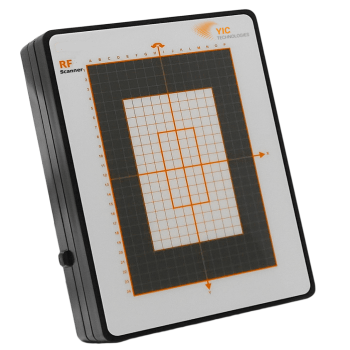
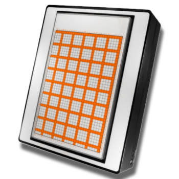
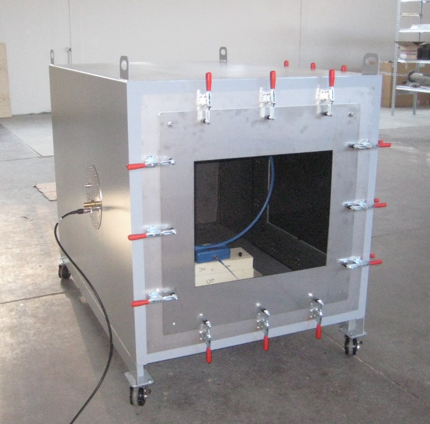
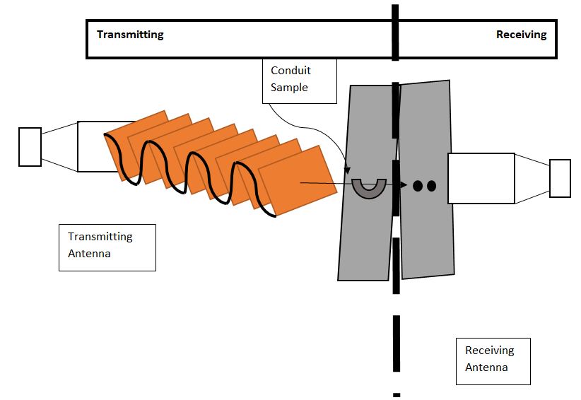
All samples that qualify for this testing must be a) some kind of enclosure; b) must be applied as a shield. Some examples of the enclosure vary greatly as there is a vast range of enclosures available. These can include and are not limited, glass windows, conduit, even nanomaterials such as carbon nanotubes. As long as it will house some kind of material in some capacity, such as a conduit with wire sent through, then the sample would qualify. See the figure below shows an example with conduit. On the transmitting side, the conduit is connected to the test chamber bulkhead (access panel) and has a signal being transmitted through it; on the receiving end is the opening of the conduit where the signal is measured to see the signal loss (attenuation) for the overall shielding effectiveness of the sample.
The test setup is the same as other shielding effectiveness, first determining the dynamic range of the unit/sample and the actual measurement of the signal for the sample in question.
MIL-STD-907B: Engineering, Design, And Shielding Effectiveness Criteria For Expandable and Non-Expandable Shelters
The single purpose for the MIL-STD-907B standard is for the development and design with rigid walled shelters. A few examples include a Radio Room, Antenna Tower Base Shelter, Power Shelter, Electrical Equipment Shelters, Instrument Shelter – Meteorological, among others. Three lines of criteria must be used in the design and engineering stage such that there will be effective shielding effectiveness:
- Achieve required performance and versatility by shelters.
- Minimize personnel man-hours to strike mobile shelters.
- Establish design standards of tactical shelters within the Agencies and Departments for the Department of Defense.
It is essential that these considerations are taken seriously when designing and engineering, because if a failure occurs, the Department of Defense would fail, and remove one from consideration.
According to the Department of Defense, there are five classes of shelters that would be categorized for applying this standard. The five categories are given a specific class, and are the following:
- Class 1: Non-Expandable Shelters. These are shelters that have equivalent sizes and shapes in any form of transportation necessary.
- Class 2: Expandable shelters. These are shelters that can expand in size and shape (can be made larger). However, they must fulfill an expansion ratio of 3-1, or less. Different shapes are also applicable.
- Class 3: Highly Expandable Shelters. These have expansion ratios larger than 3-1 to the transport size.
- Class 4: Knockdown shelters. Shelters that are reduced in height with exact items included inside for transportation.
- Class 5: Large Area Shelters. Shelters that are disassembled and packed in dedicated or general-purpose containers for shipment.
MIL-STD-907B follows the MIL-STD-285 standard, only with the following exceptions regarding test frequencies and test point locations:
- Magnetic Field Frequencies: 150 kHz
- Electric Field Frequencies: 200 kHz, 1 MHz, 18 MHz, 300 MHz
- Plane Wave: 400 MHz, 1 GHz, 10 GHz
- Test Point Locations: Following the MIL-STD-285 standard, one location per panel at the mid-point, and one location per vertical corner.
NSA 94-106 MEASURING THE EFFECTIVENESS OF ELECTROMAGNETIC SHIELDING ENCLOSURES
The NSA 94-106 (ex NSA 65-6) is known as the parallel setup, where both transmitting and receiving antennas are in parallel planes, and parallel with the plane of the sample under test.
To perform the following test we need the equipment:
- Continuous-wave (CW) source, 1 kHz to 10 GHz.
- Transmitting and receiving magnetic field antenna set covering 1 kHz to 1 MHz.
- Transmitting and receiving electric field and plane wave antenna set covering 1 kHz to 10 GHz.
- Receivers or spectrum analyzers covering 1 kHz to 10 GHz with adequate dynamic range to measure the attenuation.
The magnetic and electric field attenuation tests shall be performed with the antennas located directly opposite each other and separated by a distance of 61 centimeters (24 inches) plus the wall thickness.
Magnetic field attenuation shall be measured at 1 kHz, 10 kHz, 100 kHz, and 1 MHz.
Electric field attenuation shall be measured at 1 kHz, 10 kHz, 100 kHz, 1 MHz, and 10 MHz.
The plane wave attenuation test shall be performed with the transmitting antenna placed at least 6 meters distant from the enclosure surface (if possible) and the receiving antenna set no closer than 5.1 centimeters (2 inches) from the wall.
Plane-wave attenuation shall be measured at 100 MHz, 400 MHz, 1 GHz, and 10 GHz frequencies.
Attenuation tests shall be performed around the entire door frame, air ducts, filters, and through any accessible joint or penetration.
The magnitude and location of the maximum signal level emanating from the enclosure shall be determined by testing at least four locations.
The selection of testing locations should include not only walls but the floor and ceiling too.
NSA 65-6
Shielding effectiveness (SE) test following the Standard NSA-94-106 which replaces the Standard NSA-65-6 describes general specifications radio-frequency (RF) shielded enclosures for communications equipment.
EN IEC 50147-1 MEASURING THE EFFECTIVENESS OF ELECTROMAGNETIC SHIELDING ENCLOSURES
This standard IEC-50147-1 applies to measurements of shielding attenuation of shielded enclosures (chambers, rooms) in the frequency range 9 kHz - 40 GHz. The object of this standard is to establish a common measurement procedure for validating the shielding effectiveness of a shielded enclosure.
Shield Attenuation Measurement
The measurement is normally carried out with all the shielding components in place and, in the case of filters, with all wires and cables connected.
NOTE: The procedure is derived from NSA 65-6; National Security Agency Specification for R.F. Shielded Enclosures for Communication Equipment.
Test equipment
The following types of equipment shall be used in performing that shield attenuation test, depending on the frequency range given in the specification of the enclosures. The measurement equipment shall have sufficient dynamic range to enable the test to be performed:
- CW signal sources cover 9 kHz to 40 GHz with adequate frequency stability. If unavailable in the microwave region (1-40 GHz), pulsed sources may be substituted.
- NOTE: The starting frequency for shield attenuation measurements maybe 10 kHz if the measurement equipment offers no other alternative.
- Loop antennas for magnetic field measurements
- Tunable of broadband dipoles, monopoles with ground planes for electric field and plane wave measurements, and horn antennas for plane waves at microwave frequencies.
- Probes for joint leakage tests.
- Receivers with adequate sensitivity.
Acceptance tests
Measurements shall be taken at several positions around the enclosure as given in the specification of the enclosure. In general, these measurements are made before absorber installation.
If the ambient noise level is low enough, all tests should be run with the receiver outside and the transmitter inside the enclosure.
Leakage test
Prior to acceptance tests, leakage tests should be made all around the door frame, through accessible joints, around the filters, and all around the air ducts. In addition, the magnitude and location of the maximum signal level emanating from the enclosure should be found by moving the antennas to at least four locations, preferably on different walls.
Electric and magnetic field measurements
Electric and magnetic field attenuation tests (reference measurements) shall be made with the antennas located directly opposite each other and separated by a specific distance plus the wall thickness.
Magnetic fields shall be measured with the loops parallel to a wall panel directly opposite each other.
Recommend test frequencies for magnetic fields are 10 kHz, 100 kHz, 1 MHz, 10 MHz, and 30 MHz, and 10 MHz and 30 MHz for the electric fields.
Plane-wave measurements
Measurements shall be taken at the frequencies 100 MHz, 400 MHz, 1 GHz, 10 GHz, and 40 GHz at least, depending on the frequency range given in the specification of the enclosure.
EN IEC 61587-3 Mechanical structures for electronic equipment - Tests for IEC 60917 and IEC 60297 - Part 3: Electromagnetic shielding performance tests for cabinets and subracks
IEC 61587-3:2013 specifies the tests for empty cabinets and subracks concerning electromagnetic shielding performance, in the frequency range of 30 MHz to 3 000 MHz. Stipulated attenuation values are chosen for the definition of the shielding performance level of cabinets and subracks for the IEC 60297 and IEC 60917 series. The shielding performance levels are chosen with respect to the requirements of the typical fields of industrial application. They will support the measures to achieve electromagnetic compatibility but cannot replace the final testing of compliance of the equipped enclosure. This second edition cancels and replaces the first edition issued in 2006. It constitutes a technical revision. The main technical changes with regard to the previous edition are as follows. This edition corrects the errors of EM code descriptions and the frequency range for the shielding performance is extended up to 3 000 MHz. Keywords: Electromagnetic, Shielding, Cabinets, Subracks
ANSI/SCTE 48-3 Test Procedure For Measuring Shielding Effectiveness Of Coaxial Cable And Connectors Using The GTEM Cell
This document details the procedure for measuring the Shielding Effectiveness (S.E.) of coaxial cable and connectors using the Gigahertz Transverse ElectroMagnetic (GTEM) cell. More particularly, this procedure applies to measuring the S.E. of 75 Ohm braided coaxial drop cables and connectors presently used within the broadband communications industry. S.E. measurements can be performed with or without the affixing coaxial connectors removed from the measurement.
 Click here to see all of our articles