Pre-Compliance Testing Tools: Designing for EMC Compliance from the Start
Pre-Compliance Testing Tools: Designing for EMC Compliance from the Start
Abstract / Introduction
Electromagnetic Compatibility (EMC) failures remain one of the leading causes of delays, redesigns, and added cost in electronic product development. Engineers often only discover these issues late in the development cycle during final certification tests, when fixes are costly and time-consuming.
Pre-compliance testing allows design teams to bring EMC evaluation forward into the design and prototype stages. By identifying conducted and radiated emissions issues early, engineers can correct them with minimal cost and ensure higher confidence before entering an accredited test lab.
This paper provides a practical overview of tools and methods for pre-compliance testing, focused on conducted emissions, radiated emissions, and low-cost immunity checks. Featured solutions include the EMSCOPE, EMScanner, EMProbe, and the EM-Field Probe Kit. Case studies and examples highlight how these tools accelerate troubleshooting, improve reproducibility, and empower design engineers to make informed EMC design decisions with certainty rather than guesswork.
1. Why Pre-Compliance Testing Matters
Modern circuits run at higher switching speeds, tighter layouts, and higher power density than ever before. This makes them inherently more prone to radiated and conducted emissions problems. While final certification (FCC, CISPR, ISO, MIL, etc.) is mandatory, it should not be the first time EMC behavior is evaluated.
Pre-compliance testing provides:
- Rapid feedback during design iterations
- Visualization of emission hot spots on PCBs, harnesses, or enclosures
- Data-driven design fixes before expensive redesigns
- Confidence that products will pass formal compliance testing the first time
Put simply: catching EMC issues during design saves money, time, and reputation.
2. Conducted Emissions Pre-Compliance with EMSCOPE
2.1 Fundamentals
Conducted emissions are unwanted RF currents traveling along power and signal lines, usually in the 150 kHz – 30 MHz range. These can be:
- Differential Mode (DM): currents flowing between conductors (line-to-line) [a]
- Common Mode (CM): currents flowing equally on all conductors relative to ground [b]

Knowing whether noise is CM or DM is critical to applying the correct filter or layout fix.
 2.2 The EMSCOPE Solution
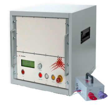
The EMSCOPE is a compact, affordable, and powerful conducted emissions analyzer. Unlike traditional spectrum analyzers, EMSCOPE is designed specifically for EMC engineers:
- Real-time CM/DM separation and analysis
- Excellent visuals for reporting: results are displayed in a clear, intuitive way for both engineers and managers
- Store and recall measurements: track results across the entire development cycle
- Correlate fixes to results: know what worked and what didn’t
- Size components with confidence: avoid “over-designing” filters out of fear; design exactly to requirements
- True compliance receiver inside: not just an analyzer—EMSCOPE gives certainty, not estimates
With EMSCOPE, conducted emissions failures are no longer unpredictable. Any design engineer can become an “EMI master,” knowing exactly how a product will perform before walking into a test lab.
|
 2.3 Expandability
The EMSCOPE integrates seamlessly with additional tools:
- LISNs (Higher Current or 3-phase)
- Current probes
- Near-field probes
- Antenna inputs
This makes it more than a conducted emissions tool—it’s a flexible platform for broader EMC validation.
2.4 Example: Switching Regulator
- Measurement: DM peaks at 300 kHz and 600 kHz harmonic detected
- Diagnosis: Input capacitor poorly placed; insufficient DM filtering
- Fix: Re-routed return paths; added X-capacitor
- Result: Noise reduced below CISPR 25 Class 5 limits; compliance achieved on first formal attempt
3. Radiated Emissions Pre-Compliance
3.1 Challenges
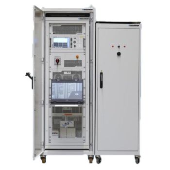
Formal radiated emissions testing requires:
- Large semi-anechoic chambers
- Precision antennas and receivers
- Expensive scheduling and long lead times
This makes them impractical during iterative design. Engineers need fast, localized, and repeatable tools.
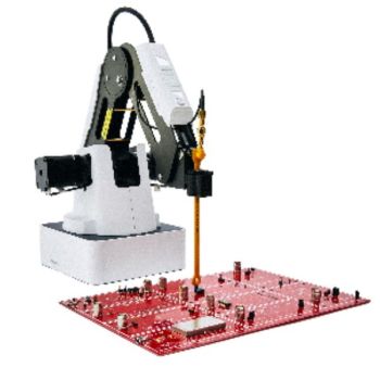
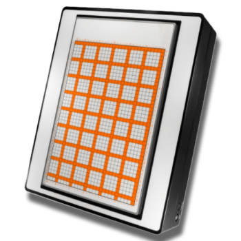
 3.2 EMScanner
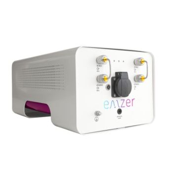
The EMScanner is a 2D planar near-field scanner for PCBs and subsystems.
- Real-time heatmaps show emission hot spots
- Full spectrum coverage up to multiple GHz
- High reproducibility—results are consistent across users and labs


- Clear visuals for communication—engineers can show before/after fixes
Case Example: A 48 MHz microcontroller clock leaking at 144 and 240 MHz.
- EMScanner identified the hot spot where the trace crossed a split ground plane.
- Fix: rerouted the trace and added a series resistor.
- Outcome: >15 dB reduction; compliance passed.

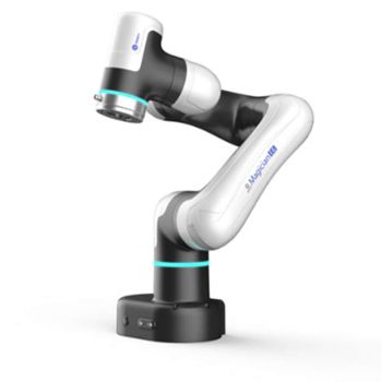
3.3 EMProbe
The EMProbe offers complementary strengths to the EMScanner:
- Ideal for large PCBs or assemblies
- Can reach between components where planar scanners cannot
- Highly reproducible and consistent
- Works well for scanning cables, harnesses, and connectors
Case Example: A 1.5 m harness radiated at 10 MHz.
- EMProbe localized leakage at the DC/DC output connector.
- Fix: added common-mode choke + better bonding.
- Result: 12 dB reduction at 10 MHz.
3.4 EMScanner vs. EMProbe
- EMScanner: Faster, more reproducible for PCB-level scans; best for visual heatmaps.
- EMProbe: More versatile for larger boards, cables, and detailed probing between structures.

 Both tools can be used interchangeably in some cases, but together they form an advanced diagnostic toolkit.
3.5 EM-Field Probe Kit
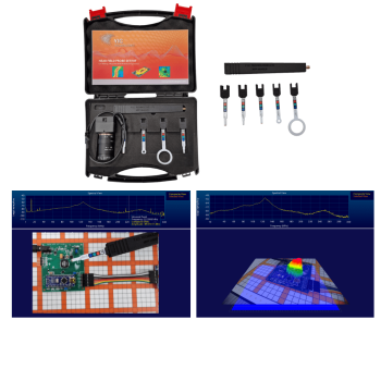
For teams on tighter budgets, the EM-Field Probe Kit provides a handheld probe with an integrated camera, using the same software to overlay emissions data onto a live image.
- Advantage: Fraction of the cost of EMScanner/EMProbe.
- Limitation: Not reproducible in exact level and location—best for quick checks, not formal reports.
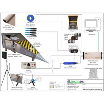
4. Antenna-Based Quick Checks
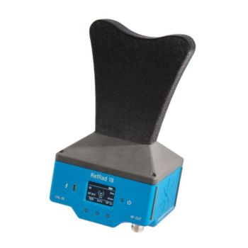
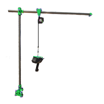
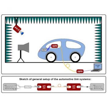
While EMScanner and EMProbe target near-field diagnostics, antenna-based setups are a valuable supplement for far-field confidence checks.
- Once critical emission frequencies are identified, you can set up a broadband antenna at 1 m, 3 m, or 10 m to check how the emissions appear in a quasi-far-field environment.
- By focusing only on the known critical frequencies, ambient noise becomes less distracting, since you are not searching blindly across the spectrum.
- Although you may lack a turntable or automated antenna mast, experience with your products will guide where emissions originate—common sources include I/O connectors, cable interfaces, and display modules.
- This setup is not a replacement for chamber measurements but provides useful context: “How do my emissions look at a few meters, compared to regulatory limits?”
- Use this only as a confidence check; reproducible development work should still rely on EMScanner and EMProbe.
5. Communication and Reproducibility
One of the hardest parts of EMC debugging is explaining issues to non-EMC stakeholders.
- Tools like EMScanner and EMSCOPE produce intuitive visuals that make problems obvious.
- Reproducibility ensures multiple engineers can obtain the same results, reducing debate and wasted effort.
- Stored results (EMSCOPE) enable clear documentation across the design cycle.
6. Summary of Benefits
|
Tool |
Focus |
Key Value |
Best Use Cases |
Limitations |
Cost Level |
|
EMSCOPE |
Conducted emissions |
Real-time CM/DM analysis, true receiver inside, excellent visuals, data storage |
Power supplies, switching regulators, EMC filter design |
Limited to 30 MHz for conducted work |
$$ |
|
EMScanner |
PCB/subsystem emissions |
2D RF heatmaps, reproducible, fast |
PCB layout debug, component-level emissions |
PCB size limited to scanner bed |
$$$ |
|
EMProbe |
Cable, large PCB, connector emissions |
Flexible probing, reproducible, detailed diagnostics |
Harnesses, enclosures, large boards |
Slower than EMScanner |
$$ |
|
EM-Field Probe Kit |
Handheld visualization |
Camera overlay, lowest cost |
Quick checks, demos, non-critical debugging |
Not reproducible in exact level/position |
$ |
|
Antenna-based checks |
Far-field validation |
Confidence check at 1m/3m/10m, focus on known frequencies |
Supplemental far-field comparison |
Limited accuracy vs. full chamber; no mast/turntable |
$ |
7. Conclusion
For circuit design engineers, pre-compliance testing is no longer optional. It is a practical, cost-saving design step that transforms EMC from a “last hurdle” into a predictable, manageable parameter.
- EMSCOPE makes conducted emissions predictable and visual, giving engineers confidence instead of uncertainty.
- EMScanner and EMProbe provide fast, reproducible diagnostics for radiated emissions.
- EM-Field Probe Kit offers a low-cost entry point to visualize emissions.
- Antenna-based checks add far-field confidence when critical frequencies are already known.
By integrating these tools into your workflow, you can:
- Eliminate EMC surprises at certification
- Shorten development cycles
- Reduce filter and shielding overdesign
- Ensure first-time compliance success
With today’s pre-compliance tools, any design engineer can be their own EMC expert.