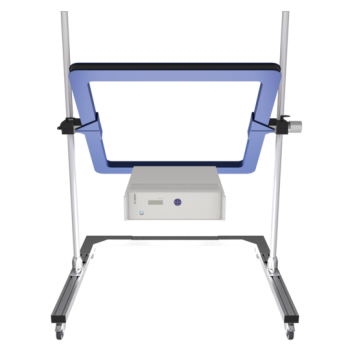
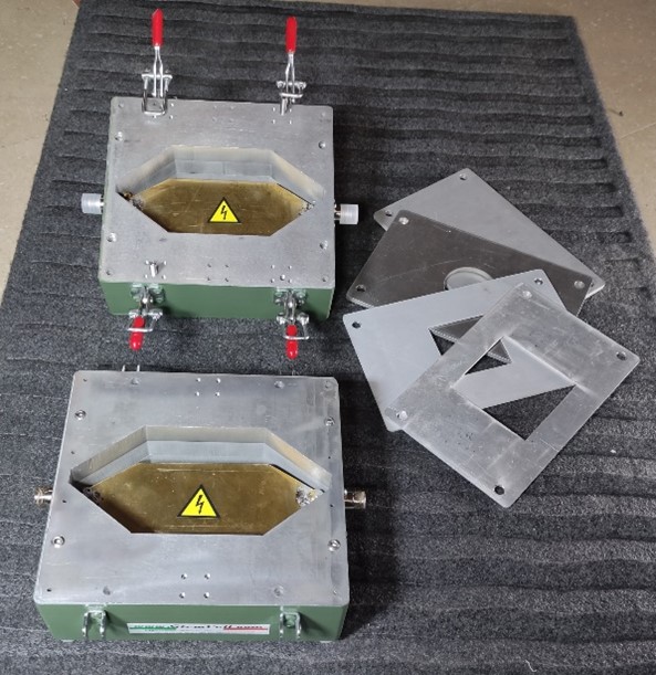
Dual TEM Cell (DTEM) used for Shielding Effectiveness Testing of materials
Dual TEM Cell (DTEM)
A dual TEM Cell test fixture is the only one that can separate the electric and magnetic field couples. Both the near-field and the far-field measurements can also be measured by this technique. The Dual TEM Cell System consists of two TEM cells, coupled through an aperture. The system has four ports as shown and numbered in Figure 1.
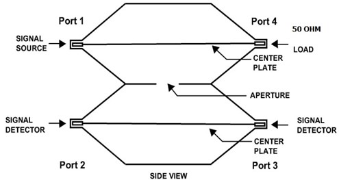
Fig.1
The source is connected to the driving cell at port 1 terminated at 50 Ohm with port 4. Ports 2 and 3 are on the sensing cell. Port 2 is on the same end as port 1. The Dual TEM Cell System allows studying the electric and magnetic field couplings separately because of having two receiving ports.
The source is connected to the driving cell at port 1 terminated at 50 Ohm with port 4. Ports 2 and 3 are on the sensing cell. Port 2 is on the same end as port 1. The Dual TEM Cell System allows studying the electric and magnetic field couplings separately because of having two receiving ports. The TEM cell consists of a section of rectangular coaxial transmission line (RCTL) with two tapered sections at each end. The taper is used as a transition to match the RCTL to standard coaxial cable characteristic impedance connectors at the two ports of the cell. The center inner conductor, consisting of a tin metallic septum, is fixed by two dielectric supports. The cell is used as a broadband amplitude and phase linear transducer of RF signals into field strengths. The field inside the cell is uniform and so it is a good approximation to simulate a plane wave in open space (far-field). Since the TEM cell operates in the bi-directional mode it is assumed that two cells coupled through a common aperture may be used as a radiated field measurement system. The coupling between cells through their common aperture yields the basic result that the dual-cell correct operation relies on. Providing the upper side of the TEM cell with an aperture, the generated field, which is known and uniform, couples into a second similar above-standing cell. When mounting the shielding material sample on the aperture, the coupling between the source cell and the transducing one is reduced. The amount of this coupling reduction is a direct measure of the shielding effectiveness of the sample material under test.
The measurement system is made up with:
Both cells are terminated on their characteristic impedance to ensure a low VSWR level and to allow for the TEM mode propagation only. An automated PC-based control system handles both exchanging transmissions between instruments and data collection.
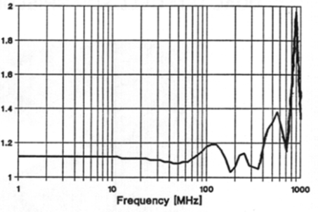
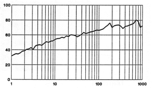
| VSWR | DTEM dynamic range [dB] measured with 0 dBm input, 1 kHz RES BW |
 |
 |
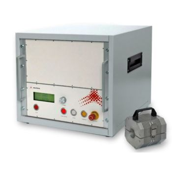
DTEM1000
Shielding Effectiveness Definitions
The measurement has a substituting approach and therefore is performed through two phases: In the first phase, called the calibration phase, the transduced signal power level is measured in a free aperture condition;
in the second phase, the same measurement is accomplished by mounting the sample on the aperture. The shielding effectiveness (SE) is so defined as:
SE = 10 Log A/B
where:
A = signal power level measured without the test sample
B = signal power level measured with the test sample mounted
 |
 |
DTEM 3000