Demystifying the DEF STAN 59-411 LISN Design Tips and Explanations
Demystifying the DEF STAN 59-411 LISN Design Tips and Explanations
Written By: Peter Green, Director at The Conformity Assessment Business And Equipment Calibration Business
Introduction
I have been designing and building Line Impedance Stabilisation Networks (LISNs) for a number of years now. The portfolio of LISNs I make covers DEF STAN 59-411, MIL STD 461, RTCA DO160 and CISPR 25. Currents range from 12 A right up to 150 A. With voltages up to 1500 V. I have put my contact e-mail at the end of this article should anyone wish to enquire about a purchase or having some custom LISNs specifically designed.
The other company I help run – The Equipment Calibration Business, performs UKAS (ISO 17025) accredited calibrations of LISNs and CDN’s amongst other things, so if you need a calibration then get in touch.
This article concentrates specifically on DEF STAN 59-411, but the design tips covered in the latter part of this article can be applied to any LISN design.
LISNs are used in virtually every test setup in DEF STAN 59-411. They are a relatively cheap test item when compared to a test receiver or amplifier, but if faulty can make a big difference to an EUT’s emission profile and how it reacts to certain immunity tests. So, without a doubt, they are a key piece of test equipment that requires regular calibration.
DEF STAN 59-411 LISNs are based on a 50 ? // 5 µH impedance profile. One of the main jobs of a LISN is to stabilise the impedance of the power supply to the EUT, for DEF STAN 59-411 this is from 1 kHz up to 400 MHz. This makes measurements much more repeatable. Consequently, results should be similar across all measurement setup locations irrespective of the laboratory performing the test. The impedance is chosen to represent real-world installation scenarios where the inductance of the supply cable to a power source is adequately simulated by the LISN impedance.
LISNs don’t just stabilise the supply impedance, they also act as a filter to high frequency noise from the power supply to the EUT. However, the filtering action of an LISN is somewhat fixed by the design constraints required to achieve the impedance curve.
LISNs also serve to act as a coupling device for measurements by connection to a receiver. For most test setups, however, the RF port on the LISN is terminated with a 50 ? load calibrated across at least the range of intended use (up to 400 MHz in the case of DEF STAN 59-411). The 50 ? load is essential for maintaining the correct LISN impedance when in use, so it is important to separately verify any 50 ? loads used as terminations for LISN RF ports.
DEF STAN 59-411 LISN impedance
The following diagrams show the required LISN impedance across the range 1 kHz to 400 MHz. For calibration of Impedance the LISN supply port is left open circuit. This is not the same as an automotive LISN of the same design and the reason for this is the lower calibration frequency. The calibration from 1kHz up takes into account and verifies the 10uF internal capacitor, which would be taken out of the circuit if the port was connected to LISN ground.
Figure 1: DEF Stan 59-411 Low-frequency LISN impedance profile 1 kHz to 100 kHz
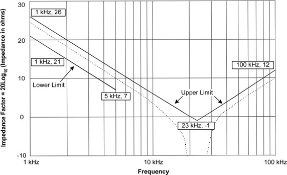
No lower limit is applied between 5 kHz to 100 kHz
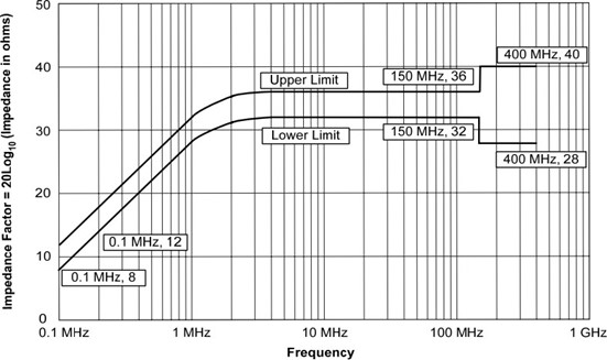
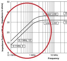
Figure 2: DEF Stan 59-411 High frequency LISN impedance profile 100kHz to 400 MHz
LISN design
DEF STAN 49-411 contains a schematic diagram for a suggested LISN design. This provides a good basis for meeting the specified Impedance profile, but in most cases tweaks to the design are required in order to meet the impedance across the full band, especially above 100 MHz. This article will cover some practical steps to take for budding LISN builders to help with this process together with an explanation of how the overall impedance curve is achieved.
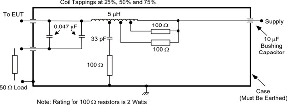
Figure 3. DEF STAN 59-411 Suggested LISN circuit diagram
The three bands of impedance from 1 kHz to 400MHz
The following explanation is a simplified version of how the overall impedance curve is made up. There are lots of additional factors at play in the construction of a LISN that make up the overall impedance curve, but generally these are unwanted factors that adversely affect the wanted ideal impedance. These will be discussed in a bit more detail later in this article under practical construction tips.
Band 1 (1kHz to 23 kHz)
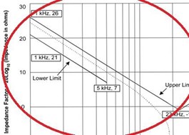
Over this frequency band, the front end coupling capacitors and 50 ? RF load provide a minimum influence on the impedance at the EUT port. The capacitive reactance of each 0.047 µF capacitor in series with the 50 ? RF load is over 100 ? at 23 kHz and with an impedance requirement of practically 0 ? at 23 kHz it is easy to see how these components don’t really have any influence.
The impedance curve up to 23 kHz is essentially due to the reactance of the 10 µF internal capacitor at the supply end of the LISN. This is 16 ? at 1 kHz and 0.7 ? at 23 kHz. The 5 µH inductor does play a part in achieving the LISN
impedance across this range but only insofar as exhibiting a really low inductive reactance which at it’s maximum at 23 kHz is still only 0.7 ?, this low reactance then allows the 10 µF capacitor to have more influence at the EUT port.
In the frequency range up to 23kHz therefore, the impedance curve simply approximates the capacitive reactance frequency response of a 10 µF Capacitor.
Band 2 (23 kHz to 5 MHz)
In this frequency band, the influence of the 5 µH inductor starts to come into play. As do the front end 0.047 µF capacitors and 50 ? RF load. At 23 kHz the inductor has an impedance of 0.7 ?, but this rises to 157 ? at 5 MHz. At the
same time the reactance of the RF coupling port capacitors drops from 70 ? at 23 kHz to 0.3 ? at 5 MHz, essentially presenting just the 50 ? RF load as the main contributor to the overall impedance. In figure 2, this effect can be seen as a gradual rise in impedance up to 5 MHz.
Band 3 (5 MHz to 400 MHz)
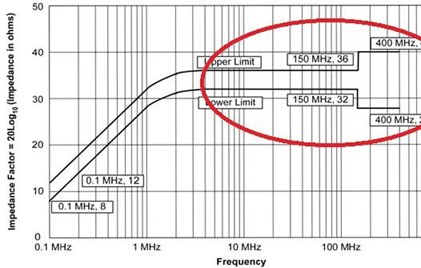
In this frequency band the reactance of the 5 µH inductor increases from 157 ? to a theoretical value of over 10 k?. This essentially just leaves the two 0.47 µF coupling capacitors and 50 ? RF load as the only contributors to the impedance at the EUT port. As the reactance of the capacitors is so low across this range the impedance is essentially made up of just the RF load. This is why it is really important to ensure the LISN RF port is terminated when in use.
Practical Design Information
When it comes to designing and building a LISN there are a host of factors to consider. This section will consider some of the main factors and tweaks to the design that help bring the impedance into specification.
Enclosure
The proximity of the enclosure to the main coil can tend to lower the inductance of the coil. This tends to exhibit in the frequency range 100 kHz to 5 MHz, the frequency range that the coil has most influence in so far as meeting the required impedance curve. The closer the enclosure is to the coil the greater the change in inductance. This effect is relatively easy to mitigate against if there is sufficient space. An additional turn or two on the coil will bring the inductance up sufficiently that when placed in the enclosure the ideal 5 µH inductance is realised.
The 10 µF capacitor
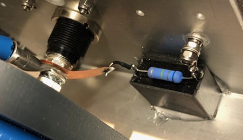
located at the supply end of this LISN is shown as a bushing capacitor in the diagram, presumably to improve frequency response. In reality though, the influence of the capacitor is limited to a few tens of kilohertz so the choice of capacitor and it’s location are not too critical. This is a part that is prone to
failure mainly due to excessive current. Keep in mind that at 400 Hz the
capacitive reactance is just 40 Ohms so the capacitors RMS current handling capability should checked. I tend to use 1.3 kV Metallized Polypropylene Film
Capacitors for this application which are good for about 12A RMS. It is also essential to add in a bleeder resistor for high voltage applications.
The main coil
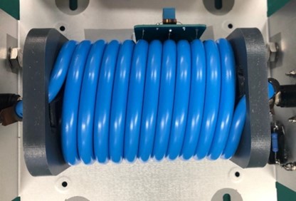
This obviously has to handle the maximum current that the LISN will be used at. The heating effect from the coil is greater than a straight conductor so if in doubt, it is important to measure the heating effect with the coil in situ within the LISN at the maximum current level that the LISN will be used at.
The coil should preferably be air cored. Inductive non-linearities due to flux saturated cores can be significant. The LISN would calibrate, but under high current draw would not perform as expected.
Depending on the geometry of the coil, parasitic inductance and capacitance may need to be countered, some level of tuning may be required to achieve a good central impedance curve. Techniques to do this are resistors across the windings and a resistor and capacitor to ground.
- For resistors across the windings 50 to 500 ? are usual values. The coil size, winding style and cable type will all influence what is required, how many are used and how many windings the resistors are connected across.
- For the resistor and capacitor to ground, I have found that values from 100pf to 0.1uF can be used. This will depend on the frequency that needs tuning. The capacitor is connected to ground via a resistor, the resistor limits the effect of the capacitor so it’s choice is key to tuning the coil. Values of 330 to 1000 ? are typical. I have found that if this is needed, it has the most effect when connected between the first third of the coil at the EUT end of the LISN. Remember the resistors and capacitor should be suitably voltage rated for the end use of the LISN.
The effects due to the coil geometry would be difficult to simulate so to some extent this is a trial and error exercise. I tend to do this as a live exercise connected up to a Network Analyser in smith chart mode so impedance changes can instantly be decerned.
For LISNs with coil tuning, it is important that any resistors connected across the windings are ideally a minimum of 2W rated. In normal use, these help tune the impedance curve of the LISN and will pass virtually no primary current. However, high frequency and surge tests cause resonances within the coil, and consequently, high currents can flow in the resistor. Burnt-out coil tuning resistors are a key reason for the calibration failure of LISNs.
Coupling Port capacitor(s)
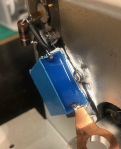
Above 5 MHz, the RF coupling port capacitor(s) are the main contributors to the flat line impedance. These will have a low capacitive reactance, and consequently, just the 50 ? RF load (or 50 ? load of the measuring receiver) form the impedance at the EUT port.
There are several factors to consider here: placement, type, and lead length.
- Placement: Parasitic effects at 400 MHz can be significant. I have found that placing the capacitor close to the body of the LISN can really help to stabilize the impedance at above 100. This should be done safely as the capacitor leads from the EUT port could have high voltage on it. I tend to use a thin polypropylene sheet between the capacitor and LISN body for added electrical insulation, but polyimide tape or other thin film insulation could be used.
- Type: the type and number of coupling capacitors can have an effect on high frequency. As long as the required coupling capacitance of 0.1 µF is realized, then ultimately, any combination can be used. Here I use Metallized Polypropylene Film capacitors. Their performance
characteristics are to some extent, unique to the specific construction size and voltage rating. Using two or even four capacitors in a series parallel combination can improve performance at high frequency.
- Lead length: ideally, the RF port should be close to the EUT port, as this means that any parasitic inductance due to lead length is kept to a minimum. If this can’t be avoided, then I use flat copper connecting strips that are 0.5mm thick and 6mm wide to form the connections.
Contact: info@confiormity-assessment.com