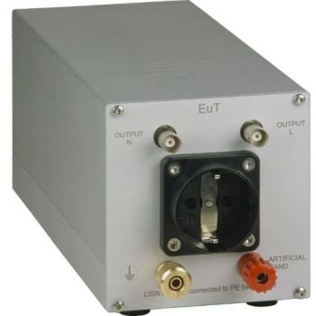
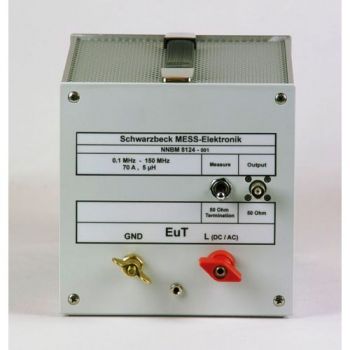
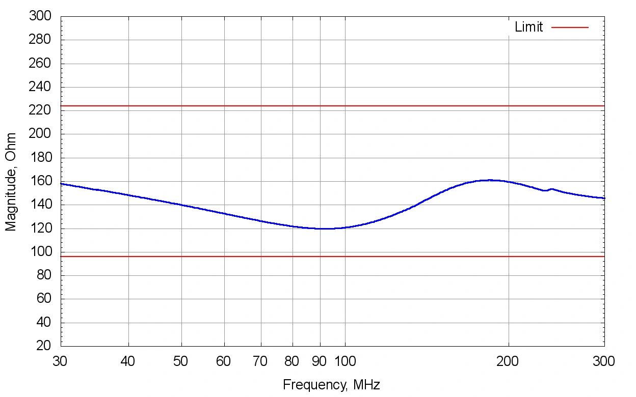
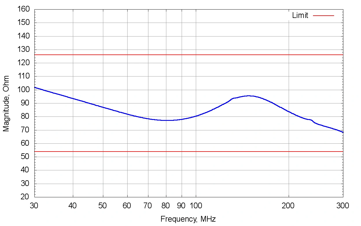
Live: 160 Ω ±40%
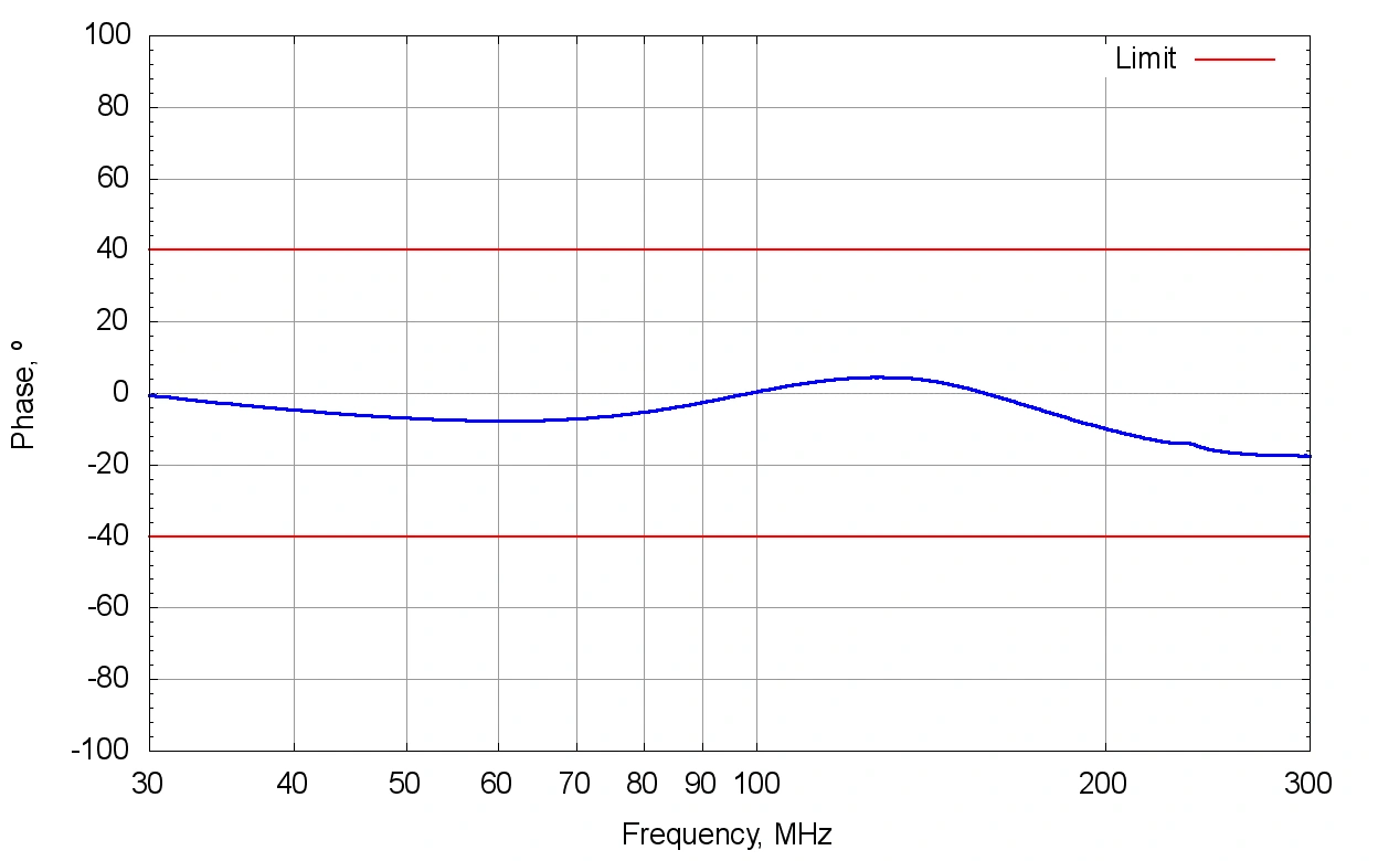
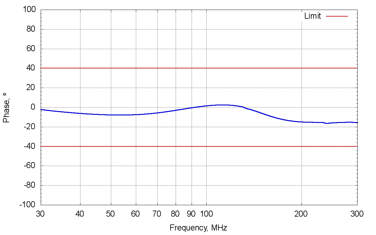
The live-terminal impedance is specified with PE bonded to reference ground (RG). The phase limit is 0° ±40°.
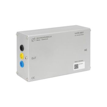
A controlled, unbalanced RF termination for the EUT mains cable.
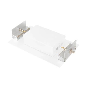
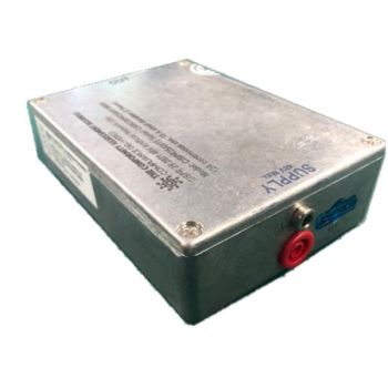
The VHFU 8802 provides unequal terminal impedances during radiated-disturbance measurements of AC-mains-powered equipment. This defined imbalance creates controlled differential-mode to common-mode conversion and offers a VHF-LISN alternative to a common-mode absorption device (CMAD).
PARTNER:
MARKETS:
CATEGORIES:
TEST STANDARDS:

Data Sheet
The live-terminal impedance is specified with PE bonded to reference ground (RG). The phase limit is 0° ±40°.
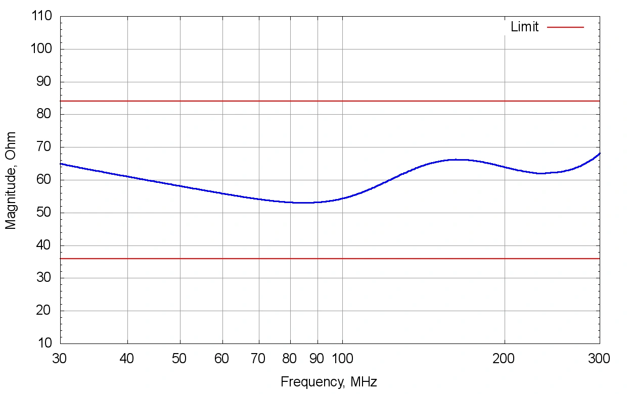
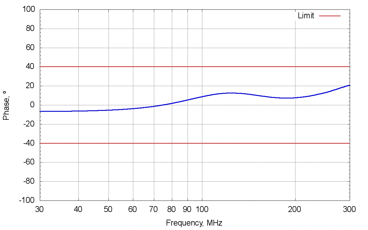
The neutral-terminal impedance is also specified with PE bonded to RG. The phase limit is 0° ±40°.
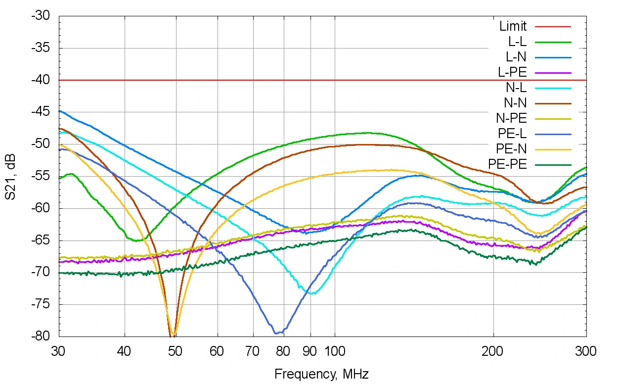
The PE terminal has a defined impedance to RG. The datasheet lists a phase limit of 0° ±40°. Typical magnitude and phase plots are shown below.
The manufacturer identifies compliance with CISPR 16-1-4, Edition 5. The VHF-LISN terminates the EUT’s mains cable for radiated disturbance testing.
Insert the device between the test-site mains outlet and the EUT mains cable at the point where the cable leaves the test volume.
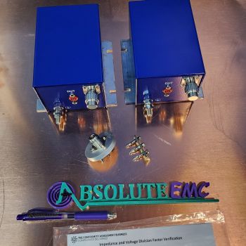
The optional IMA 8803 adapter supports impedance and isolation measurements. When measuring L and N impedance on the VHFU 8802, its PE-to-enclosure shorting adapter must be installed.
Use the grounding and cable arrangement specified for the test. RG means reference ground; EUT means equipment under test; AE means auxiliary equipment.
Ratings, connectors and mechanical details consolidated from the manufacturer’s product page and Rev. A datasheet.
Read the full datasheet →| Nominal frequency range | 30–300 MHz |
|---|---|
| Live-terminal magnitude, PE bonded to RG | 160 Ω ±40% |
| Live-terminal phase | 0° ±40° |
| Neutral-terminal magnitude, PE bonded to RG | 60 Ω ±40% |
| Neutral-terminal phase | 0° ±40° |
| PE-terminal magnitude to RG | 90 Ω ±40% |
| PE-terminal phase, per datasheet | 0° ±40° |
| Isolation, AE–EUT | ≥40 dB |
| Maximum current | 16 A |
| Maximum voltage | 1000 V |
| EUT and AE connectors | 3 × 4 mm safety laboratory jacks |
| Ground connection | 4 mm laboratory jack |
| Standard | CISPR 16-1-4 / Edition 5 |
| Housing | Aluminum |
| Dimensions | 171 × 105 × 55 mm |
| Weight | Typical 760 g |
| Optional accessory | IMA 8803 impedance measurement adapter |
Extracted from the datasheet with axes, legends and limit lines intact. Typical curves characterize the device; use the stated specifications and unit calibration where applicable.
The VHFU has unequal live, neutral and PE impedances. The VHFB uses a balanced live/neutral termination. Select the device required by the test configuration.
It is listed as an optional accessory. Its datasheet describes the required impedance and isolation measurement arrangements.
Ask about the VHFU 8802, compatible accessories and your measurement requirements.
Product inquiries for the United States, Mexico and Canada.