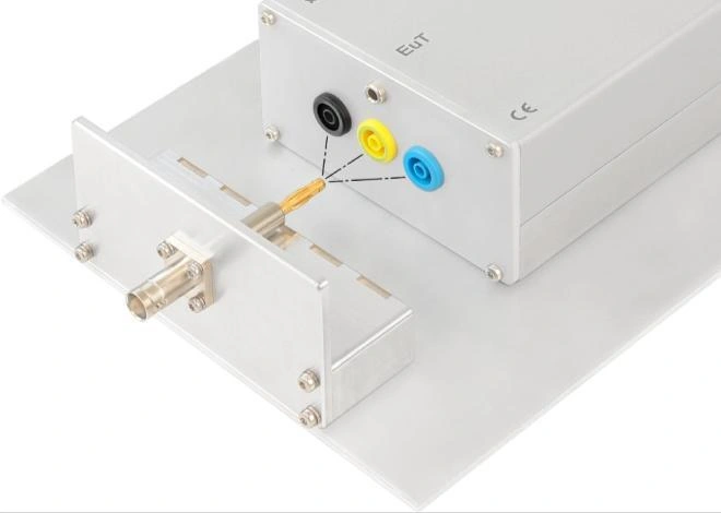
Coaxial-to-terminal transition
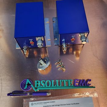
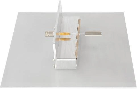
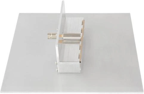
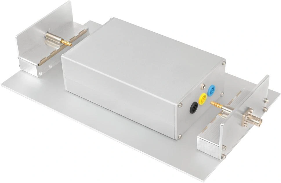
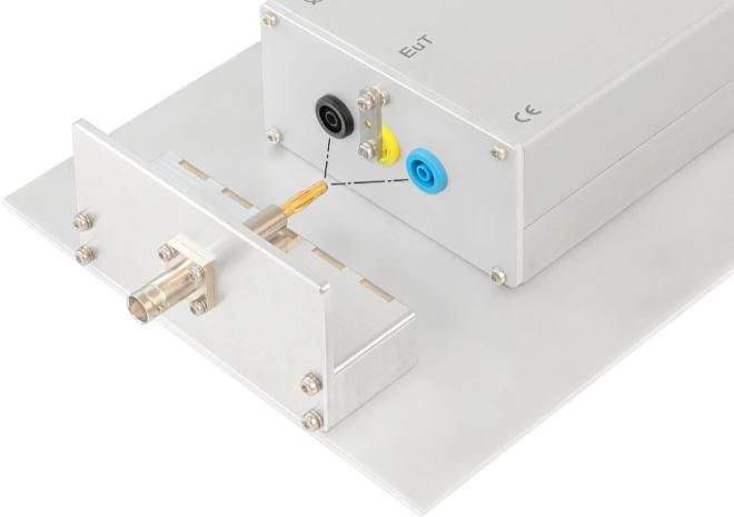
A BNC connector on a vertical metal plate feeds a solid cylindrical conductor. A banana-to-power-plug pin adapter connects that conductor to the VHF-LISN terminal.
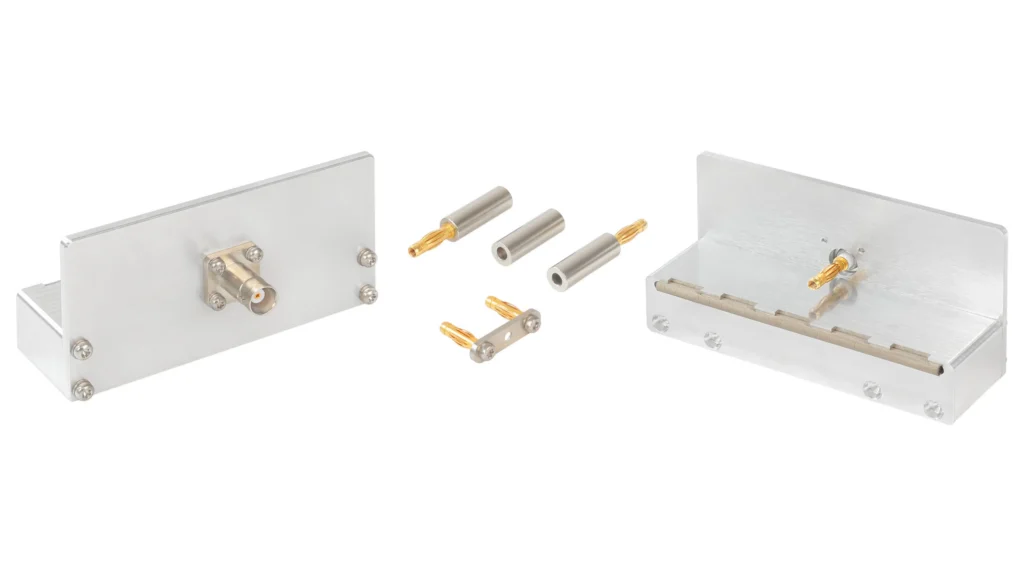
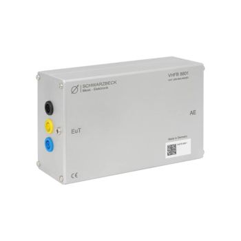
A defined measurement interface for VHF-LISN verification.
The IMA 8803 connects a vector network analyzer to the VHFB 8801 or VHFU 8802 for impedance and isolation measurements. The adapter follows the example in CISPR 16-1-4, Edition 5, and includes a reference-ground-plane extension with an EMI gasket interface.
PARTNER:
MARKETS:
CATEGORIES:
TEST STANDARDS:

Data Sheet
A BNC connector on a vertical metal plate feeds a solid cylindrical conductor. A banana-to-power-plug pin adapter connects that conductor to the VHF-LISN terminal.
The conductor sits at a defined height over a horizontal metal plate. This plate contacts the vertical adapter plate and the VHF-LISN faceplate through an EMI gasket.
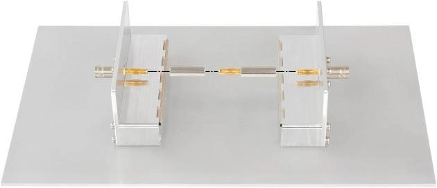
Impedance measurement uses one IMA 8803 adapter. Isolation measurement uses two adapters; the full assembly and calibration arrangements appear in the datasheet photos below.
Calibrate the vector network analyzer including the measurement cable for impedance measurement.
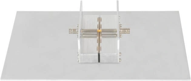
Connect the IMA 8803 Through adapter and use the VNA “Auto Length” function. The resulting electrical length should be approximately 48 mm.
Replace Through with an SR 30/4 adapter. Measure each EUT-side terminal in turn. For VHFU 8802 L and N measurements, install the VHFU 8802 Short between PE and the enclosure.
Perform full VNA calibration including both measurement adapters. During calibration, interconnect them with one SR 30/4 and one IMA 8803 Through adapter.
After calibration, replace the IMA 8803 Through adapter with a second SR 30/4.
Connect the adapters to the EUT and AE ports. Measure isolation between L, N and PE in every EUT-to-AE terminal combination.
Impedance measurement uses one adapter. Isolation measurement requires two adapters and a full calibration including the adapters.
Ratings, connectors and mechanical details consolidated from the manufacturer’s product page and Rev. A datasheet.
Read the full datasheet →| Nominal frequency range | 30–300 MHz |
|---|---|
| Nominal impedance | 50 Ω |
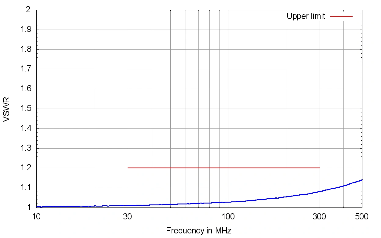
| VSWR | <1.2 |
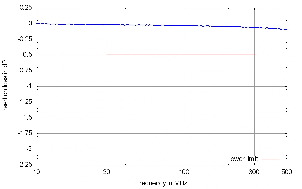
| Insertion loss | |
| Input connector | BNC female |
| Output connector | 4 mm plug |
| Standard | CISPR 16-1-4 / Edition 5 |
| Housing / plates | Aluminum |
| Weight | Typical 485 g |
| Compatible VHF-LISNs | VHFB 8801 and VHFU 8802 |
Quantities listed in the IMA 8803 datasheet. The isolation procedure requires two measurement adapters.
| IMA 8803 Part 1 | 1 |
|---|---|
| IMA 8803 Part 2 | 1 |
| SR 30/4 | 2 |
| IMA 8803 Through | 1 |
| VHFU 8802 Short | 1 |
Extracted from the datasheet with axes, legends and limit lines intact. Typical curves characterize the device; use the stated specifications and unit calibration where applicable.
Original figures extracted from the associated datasheet. Open any image to inspect the full-size figure.
The datasheet specifies one for impedance measurements and two for isolation measurements.
The specific PE-to-enclosure shorting instruction applies to L and N impedance measurements on the unbalanced VHFU 8802.
Ask about the IMA 8803, compatible accessories and your measurement requirements.
Product inquiries for the United States, Mexico and Canada.