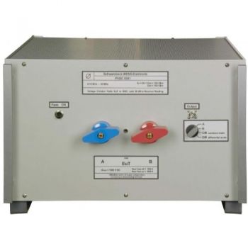
PVDC 8300, 150 kHz - 30 MHz, 100A, DC-AMN (LISN) Photovoltaic Inverters
- symmetric DC-LISN Line Impedance Stabilization Network
- 150 kHz - 3 MHz
- Current rating: 100 A (150 A 15min)
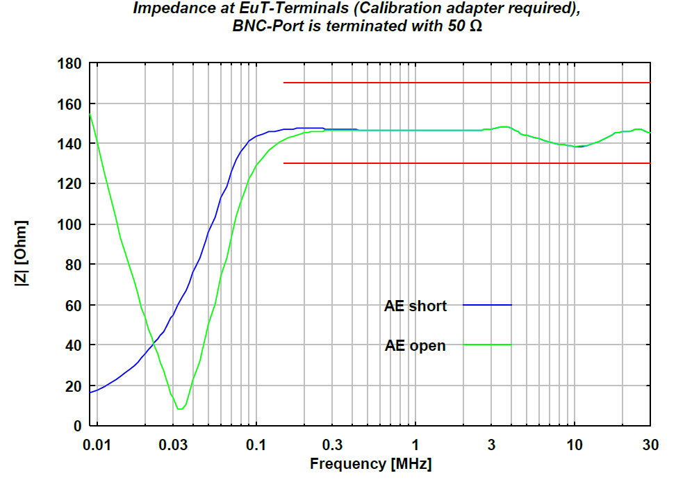
- Impedance CM and DM: (150 +/- 20) Ω
- AMN Impedance A or B: (150 +/- 20) Ω

Data Sheet
SPECIFICATIONS
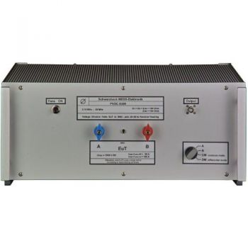
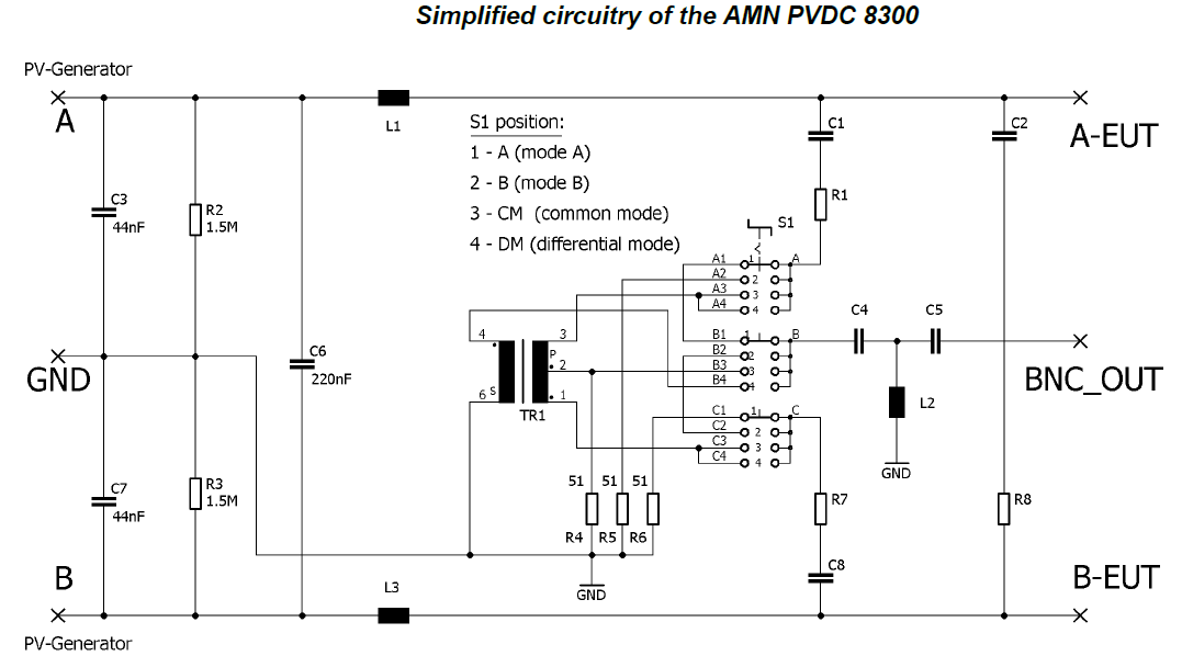
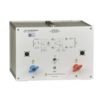
PVDC 8300, 150 kHz - 30 MHz, DC-AMN (LISN) Photovoltaic InvertersThe conducted emissions of photovoltaic inverters at the mains terminals are usually measured using LISN according to CISPR 16-1-2. The circuit concepts of PV-inverters may cause ripple currents on the DC-side of the inverter. These ripple currents are passing through the cabling and the PV-generator modules and can be radiated as magnetic fields with sometimes remarkable disturbance effects. Traditional measurements at the PV-inverters' AC terminals will not be able to reveal such disturbance phenomena. The PVDC 8300 was specially designed to measure all kinds of disturbance voltages at the DC-side of photovoltaic inverters. These are in detail the disturbance voltage of one conductor above reference ground (unsymmetrical disturbance voltage), the common-mode disturbance voltage of a pair of conductors above ground (asymmetrical disturbance voltage), and finally, the differential mode voltage between two conductors. Application: The symmetric DC-LISN PVDC 8300 can be used for measuring of the disturbance voltage in the frequency range from 0.15 MHz to 30 MHz on photovoltaic inverters. It is designed with air-core or iron-free inductors to prevent intermodulation. The permitted continuous current is 100 A with activated fans. Without fans 50 A continuous current can be supplied. Short time currents over 150 A can be applied. The temperature of the built in inductors may not exceed 150°C. The device under test is connected to the wing terminals of the front panel. The PV-generator or the PV-simulator is connected to the rear side. The capacitor C3 was limited to 0.22 μF to avoid possible malfunction of the EuT. This leads to a differential mode decoupling of more than 20 dB. If higher decoupling values are required (e.g. 40 dB or more), the use of an additional 1 μF / 1500 V DC capacitor at the AE-terminals will bring significant improvements.
|


OTHER PRODUCTS IN THE SAME CATEGORY:
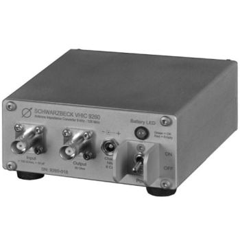
VHIC 9260, 9 kHz to 120 MHz, Impedance converter to 50 Ohm
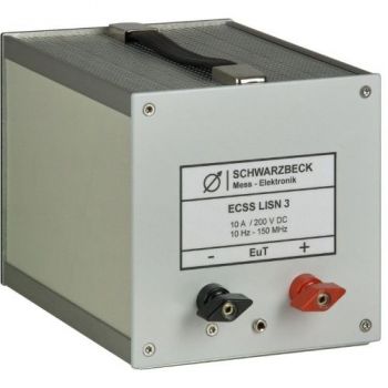
ECSS LISN 3, 10 Hz - 150 MHz, 10A, DC Lines, LISN
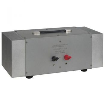
ECSS LISN 2-75A, 10 Hz - 150 MHz, 75A, DC Lines, LISN

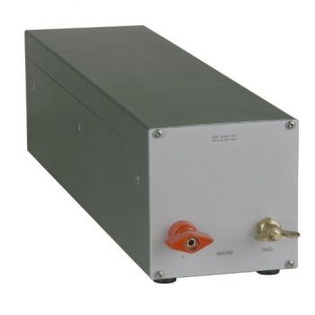
ECSS LISN 2, 10 Hz - 150 MHz, 10A, DC Lines, LISN
NPCL 8500, 3 - 148 kHz, PRIME PLC LISN
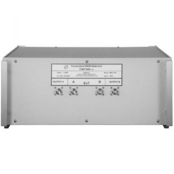
TEMP 8400, 9 kHz - 1 GHz, TEMPEST AMN (LISN)
PVDC 8300, 150 kHz - 30 MHz, 100A, DC-AMN (LISN) Photovoltaic Inverters
PVDC 8301, 150 kHz - 30 MHz, 200 A, DC-AMN (LISN) Photovoltaic Inverters
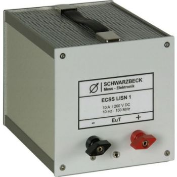
ECSS LISN 1, 10 Hz - 150 MHz, 10A, DC Lines, LISN
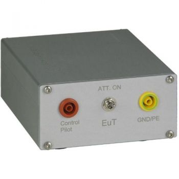
PILOT ISN, 150 kHz - 30 MHz, 1.4A, PLC
PVSM 8320, Symmetrical DC-network and LISN

AN-ABCD-300, 300 Amp Artificial Network, EV HV Testing

AN-ABCD-60, 60 Amp Artificial Network, EV HV Testing
CABCISPR2532A, CISPR 25, 5uH, 32 A LISN
CABCISPR2515A, CISPR 25, 5uH, 15 A LISN
Cx 10000-xxx-xxx, 1000V, 100 - 600 amp 10mF HV Capacitor Cabinet
NSLK 8117, 9 kHz - 30 MHz, 250V / 10A, 50 µH, 2 Path LISN
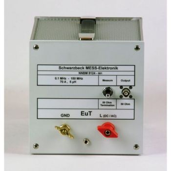
NNBM 8124, 10 kHz - 150(400) MHz, High Voltage, 70A, single path, 5µH LISN
MDS 21 C, 30 - 1000 MHz, EMI Absorbing Clamp

