
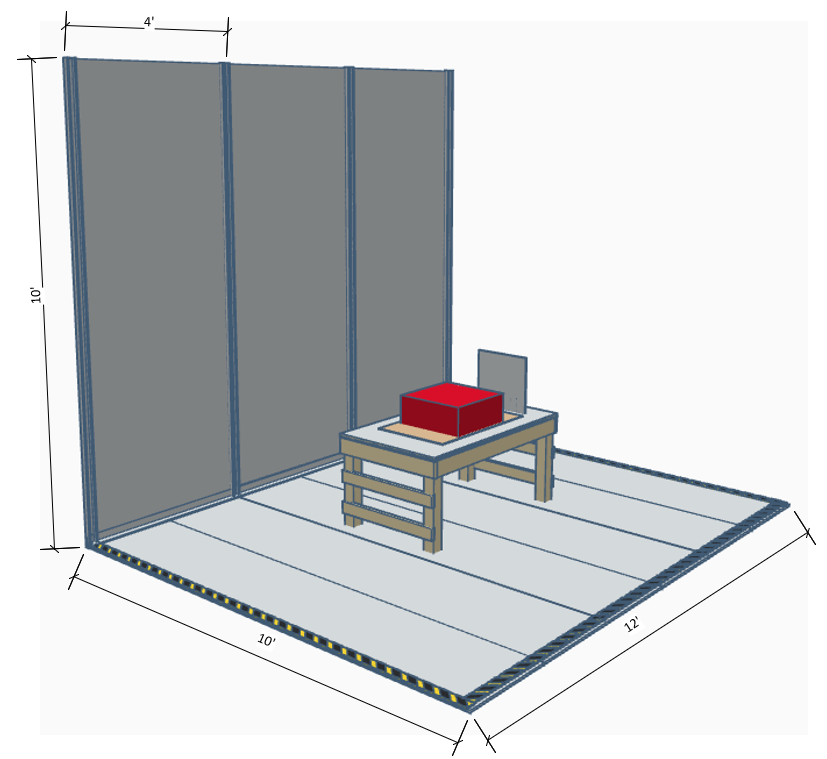
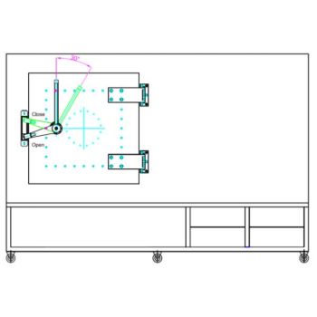
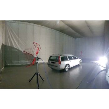
Floor Ground Plane & Vertical Wall
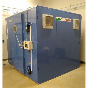
- Low-profile 12'×10' floor plane with matching vertical wall (up to 12'×10') in galvanized steel.
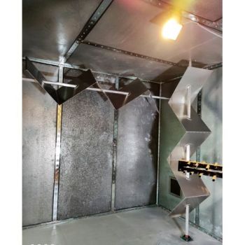
- Staggered two-layer floor design: wide metal-to-metal overlap, ultra-low impedance, almost zero step height.
- Fast install (1–2 days) with full bonding/continuity verification to the building ground or a shielded room.
- Engineered to meet IEC 61000, CISPR, and MIL-STD-461 ground-plane requirements.
- Custom sizes/materials (steel, aluminum, copper), edge ramps, LISN pads, and cable trenches available.
- Delivers repeatable EMC/ESD results by minimizing loop impedance and stray coupling paths.
PARTNER:
MARKETS:
CATEGORIES:
TEST STANDARDS:
SPECIFICATIONS
Custom Floor/Vertical Ground Plane InstallationAbsolute EMC offers a high-performance galvanized steel ground plane system designed for EMC testing environments. Low-profile, high-conductivity reference surfaces for EMC/ESD test setupsThe system includes:
Installation Time: 1–2 days, included with purchase. Why it matters
A continuous, well-bonded ground reference dramatically reduces loop impedances, stabilizes test repeatability, and keeps you aligned with IEC 61000 series, CISPR, and MIL-STD-461 layout expectations. Poor planes cost you time in troubleshooting and can invalidate data—this system fixes that.
Key Technical Features
Typical Applications
Deliverables (Typical Package)
Installation Approach (Summary)
Specification Snapshot
Options:
Requirments:
Best for pictures to be sent of the area for a better understanding before quoting.
|

OTHER PRODUCTS IN THE SAME CATEGORY:
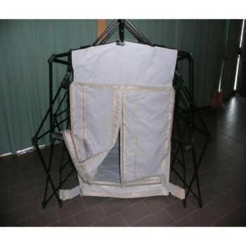
Shielded Tent
Floor Ground Plane & Vertical Wall
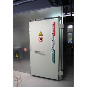
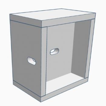
Shielded Chamber and Box Solutions
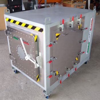
EMC SHAC-200, ~700MHz-40GHz, Shielded Box Solutions
SB3G Shielded Box – EMI & RF Protection
Reverb Chamber Retrofit(Discontinued)
Reverb Chamber (Discontinued)
VRC Reverb Tent Chamber
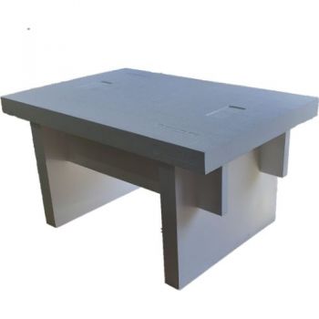
EPS Test Table Lt - low permittivity for high frequency testing
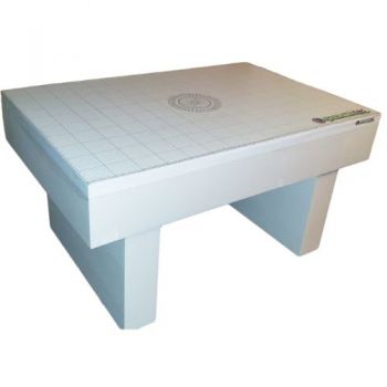
EPS Test Table - low permittivity for high frequency testing
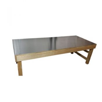
Wood Test Table Kit
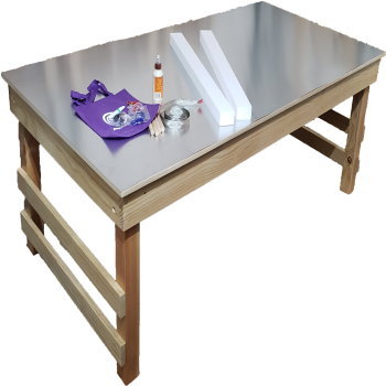
ESD Test Table Kit
Floor Ground Plane & Vertical Wall
EMC EPS 70cm Support- EUT support
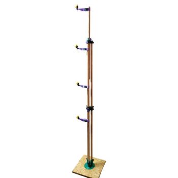
ABSOLUTE EMC Monopole Probe Stand
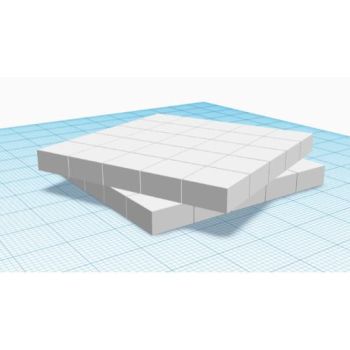
EMC EPS Pad- 5x50x50 cm, EUT support

EMC EPS Cube- 10x10x10 cm, EUT support

EMC EPS 5cm Sheets - low permittivity EUT Support for high frequency testing
EMC EPS Bar- 1m long 5cm height, EUT/cable support

