Why is it important to control and measure CDN impedance for EN61000-4-6 testing?
Why is it important to control and measure CDN impedance for EN61000-4-6 testing?
The Equipment Calibration Business carries out CDN impedance calibrations under its UKAS ISO17025 accreditation umbrella.
CDN impedance is an important part of the test level chain when testing to EN61000-4-6. In the standard, this is specified as follows:
| Frequency Band | ||
| 150 kHz – 26 MHz | 26 MHz - 80 MHz | |
| Impedance | 150 Ohm ± 20 Ohm | 150 Ohm +60 Ohm -45 Ohm |
The characterization of impedance is as important as the level setting procedure that the test laboratory typically carries out at least annually. CDN impedance can have a substantial effect on EUT test level, irrespective of the test laboratory carrying out a level setting calibration.
In busy test laboratories, there is always scope to damage the CDN to the point where the impedance requirement is not met. Having worked in EMC for 20+ years, I have seen them all! Over-voltage and transients can damage decoupling capacitors, and excess current can heat and crack the ferrite cores of the main inductor affecting its overall inductance. Even dropping them can shift windings and affect the higher frequency impedance.
A CDN with a 150 Ohm impedance and one with a 300 Ohm impedance will still level set without any issues i.e., 10 V RMS or 3 V RMS etc., so the test laboratory would think they are applying the correct level. But when those same CDN’s are used to test a product, the RF current flow and voltage across the same EUT load will be different. Depending on the impedance, this could be either more or less onerous than the standard requires.
I have set up a very simple Spice simulation to show this effect and performed some measurements at 150 kHz. This involves level setting two CDN’s with different impedances and then substituting in a 1000 Ohm resistor to simulate a EUT RF load. The CDN model is simplified as, in reality, the coupling and termination play a part in the overall CDN impedance. For this model, I have just calculated this based on the value of the inductor L1.
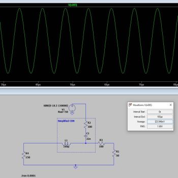
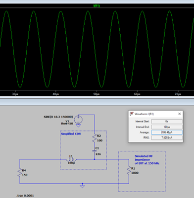
[1] With the CDN impedance set to approximately 150 Ohm (at 150 kHz). An initial calibration at 10V RMS (1.65 V RMS across the 50 Ohm load, 10 V / 6 as required by the standard). This simulates the level setting procedure that would be carried out in the test laboratory. This required a drive voltage of 18.3 V.
150 kHz of a sample EUT. This produces 7.8 mA and 7.8 V across the EUT load.
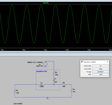
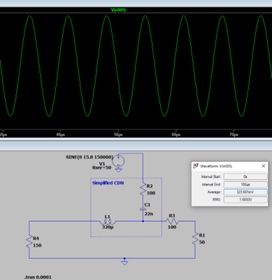
[3] With the CDN impedance changed from 150 Ohm to 300 Ohm (at 150 kHz), the level setting was carried out again for a level across the 50 Ohm load of 1.65 V RMS. Again, this simulates a calibration test level of 10 V RMS. This required a drive voltage of 15.8 V.
150 kHz of a sample EUT. This produces 8.4 mA across the EUT load.
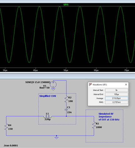
The two sets of examples show that with the same laboratory calibrated 10V test level, the current flow and voltage developed across an identical EUT load of 1000 Ohm has increased from 7.8 mA to 8.4 mA. This is 7.8 V, and 8.4 V developed across the EUT load, respectively.
This may not seem much, but it is a EUT current increase of 7 % and could make the difference between a pass or a fail for the customer and certainly affect inter-laboratory repeatability.
The Equipment Calibration Business comes to you! So to arrange for your CDN’s to have their impedance characterized in line with the requirements of EN61000-4-6, drop us a contact at ecb@equipment-calibration.com or call us on: 01494 444277