Switching Speed Requirements in Voltage Dips Testing According to IEC 61000-4-11 and IEC 61000-4-34
Switching Speed Requirements in Voltage Dips Testing According to IEC 61000-4-11 and IEC 61000-4-34
Voltage dips (commonly referred to as voltage sags) are brief reductions in AC supply voltage, typically resulting from electrical faults, large load changes, or motor startup. These disturbances pose significant risks to the functionality and reliability of electrical and electronic systems.
To ensure proper immunity of equipment to such events, international EMC standards IEC 61000-4-11 and IEC 61000-4-34 specify standardized test procedures and performance criteria for evaluating the effects of voltage dips, short interruptions, and voltage variations.
A critical aspect of these standards — and the focus of this article — is the switching speed required to simulate abrupt voltage dips, especially in systems rated up to 75 A per phase. While systems up to 16 A are readily available and relatively economical, test setups for three-phase equipment and higher current levels (approaching 75 A) become increasingly complex and costly — and for good reason.
Overview of the Standards
IEC 61000-4-11
Applies to AC-powered equipment with input current ≤16 A per phase. It defines immunity tests to voltage dips, short interruptions, and voltage fluctuations on single-phase and three-phase AC power ports.
IEC 61000-4-34
Extends similar immunity testing to equipment with input currents >16 A per phase, typically large industrial or commercial systems operating on three-phase power.
Switching Speed Requirements for Voltage Dips
A key technical requirement in both standards is the maximum allowable transition time between the nominal voltage and the dip level. This transition must occur in ≤5 microseconds (µs) to ensure a sudden and realistic voltage drop.
Transition Time Specification:
- Dip initiation and recovery must occur within ≤5 µs
This requirement is explicitly defined to prevent the Equipment Under Test (EUT) from reacting slowly to a gradually declining voltage — which could skew test results. A rapid transition more accurately emulates real-world faults, forcing the EUT to respond as it would under critical operating conditions.
Peak Current Handling and Withstand Requirements
During the rapid switching event, the switch must handle significant transient currents due to the low-impedance path created during voltage transitions. IEC 61000-4-11 and IEC 61000-4-34 define maximum surge values:
- Ipeak (Half-wave peak current):
- Duration: ≤2.5 ms
- Limit: ≤1000 A
- ISC (Short-circuit current):
- Rise time: ≤5 µs
- Peak: ≤2000 A
These high peak currents ensure that the transition occurs without impedance-induced distortion. The switch must not limit or influence the voltage applied to the EUT in any way — ensuring the EUT experiences the full severity of the dip.
The Limitation of Programmable Power Supplies
Although high-end programmable AC sources can be configured to generate voltage dips in accordance with the test levels defined in the standards, no available power supply is capable of achieving the required .
Typical AC sources have slew rates in the range of hundreds of microseconds to milliseconds. As such, a programmable AC source alone is insufficient for voltage dips testing. The transition is too slow to meet the standards, and any compensation by the EUT may invalidate test results.
Why Fast Switching Is Essential
A slow voltage ramp allows the EUT’s internal regulation circuits to adjust or compensate, which masks actual susceptibility. A sharp, abrupt dip ensures the system is tested under true worst-case disturbance conditions.
Solution: Solid-State Switching with Voltage Slew Enhancement (VSE)
To meet the strict transition speed requirement, both standards recommend the use of a solid-state switching system to instantaneously toggle between:
- Steady-state voltage source (e.g., infrastructure AC or programmable supply)
- Dip voltage source (typically a transformer tap or preconfigured low-voltage source)
System Architecture
The switch — often implemented using high-speed thyristors or IGBTs — enables rapid transfer between the two voltage levels. To emphasize its function, it is often referred to as a Voltage Slew Enhancer (VSE). Its key performance criteria include:
- Switching time ≤5 µs
- Peak current withstand: ≤1000 A for 2.5 ms, ≤2000 A for ≤5 µs
- Non-intrusive switching: no influence on EUT behavior
- Synchronized, distortion-free waveform transitions

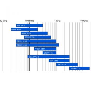
Figure 1: VSE Diagram of the input and output of HIGH SPEED switch
Example Configuration
For a 230 V, 40% voltage dip test (target voltage = 92 V), the test system includes:
- 230 V AC source (steady-state)
- 92 V dip source (e.g., transformer tap or low-voltage source)
- Solid-state switch (VSE) with fast transfer capability
- Proper load-rated cables and impedance coordination
At the moment of triggering, the solid-state switch instantly transfers the output from the nominal source to the dip source within , preserving phase and waveform synchronization.
Engineering Considerations and Safety
Designing such a switching system is inherently complex. At currents up to 75 A per phase, the switch must be physically robust and electrically resilient. The need to handle short-term high surge currents further enlarges the component and thermal management requirements.
Additionally, these systems must be designed with extensive safety interlocks, monitoring systems, and fail-safe features to protect both the operator and the EUT. This is not a simple switch — it is a comprehensive switching platform tailored to the unique demands of EMC testing.

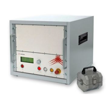
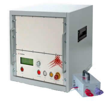
Figure 2: VSE Basic diagram with a power source
Above 75 A: Relaxed Switching Requirements
When testing equipment with input currents greater than 75 A per phase, the standards recognize the challenges of high-speed high-current switching. As a result, slower switching speeds are permitted.
In such cases, a high-performance programmable AC source may be used directly, even if the slew rate exceeds 5 µs. While the transition must still be sharp enough to represent real-world voltage dips, it is not bound by the strict microsecond-level requirement enforced at ≤75 A.
Verification and Compliance Assurance
To ensure compliance with IEC 61000-4-11 and IEC 61000-4-34, test systems must undergo detailed verification. The following parameters must be validated using calibrated measurement instruments:
- Voltage transition time: Verified to be ≤5 µs (when applicable)
- Peak current handling: Verified against Ipeak and ISC thresholds
- Waveform integrity: Ensure sine wave is not distorted during transition
- EUT response neutrality: Switching must not affect EUT operation other than the intended voltage dip
The Importance of Software Control and Reporting
Accurate and repeatable execution of voltage dip tests in accordance with IEC 61000-4-11 and IEC 61000-4-34 relies heavily on robust software control. Test automation ensures precise timing, repeatability, and synchronization with the EUT's operational cycles. Moreover, software-driven control systems facilitate integration of test parameters, switching sequences, and dip profiles with minimal operator intervention — critical for maintaining consistency across tests.
Equally important is the role of data acquisition and reporting. Validation of test results requires direct measurement of voltage and current waveforms at the EUT input terminals, with high temporal resolution. These measurements confirm that the dip transitions occur within the required ≤5 µs and that current surges remain within permissible thresholds.
All test parameters, waveform captures, and verification results must be compiled into a comprehensive test report. This documentation serves as proof of compliance and must demonstrate that the EUT was subjected to test conditions that faithfully replicate the standard’s requirements. Without proper software and detailed reporting, it is not possible to ensure full traceability or confirm that the immunity assessment meets regulatory expectations.

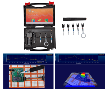
Figure 3: Screen Shot of software setup
Conclusion
Voltage dip immunity testing per IEC 61000-4-11 and IEC 61000-4-34 demands precise, high-speed switching between voltage levels. For systems rated up to 75 A, this can only be achieved using a solid-state Voltage Slew Enhancer (VSE), as no standalone programmable power source can meet the required
These solid-state systems must be carefully engineered to withstand high surge currents and maintain full test integrity without influencing the EUT. For equipment exceeding 75 A per phase, the standards provide flexibility to use slower transitions with high-performance AC sources — though care must still be taken to preserve waveform accuracy and proper test conditions.

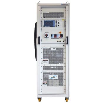
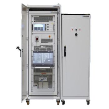
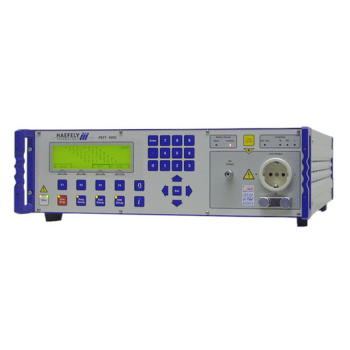
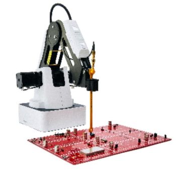
Figure 4: Example of Full System 75 amps -4-11/-4-34
References
- IEC 61000-4-11 – Electromagnetic compatibility (EMC) – Part 4-11: Testing and measurement techniques – Voltage dips, short interruptions, and voltage variations immunity tests
- IEC 61000-4-34 – Electromagnetic compatibility (EMC) – Part 4-34: Testing and measurement techniques – Voltage dips, short interruptions, and voltage variations immunity tests for equipment with input current >16 A per phase
- Regatron – Information sheet and Data sheet on high speed switching VSE PD_EMC-Testsystem-61000-4-X_EN_220426.pdf DS_TC.VSE.50.528.2WR.S_EN_221206.pdf