EN61000-4-11:2020 Standard Review
|
Document Number: |
CABSP-20-001-01 |
|
Issue: |
01 |
|
Issue Date: |
18 May 2020 |
Written By: The conformity Assessment Business
|
Standard: |
EN IEC 61000-4-11:2020 |
|
Title: |
Electromagnetic compatibility (EMC) - Part 4-11: Testing and measurement techniques - Voltage dips, short interruptions and voltage variations immunity tests for equipment with input current up to 16 A per phase |
|
Superseded Standard: |
EN 61000-4-11:2004 +A1:2017 |
|
Date of Withdrawal: |
3 March 2023 |
|
Initial Review Date: |
18 May 2020 |
|
Overall Grade of Change |
|
|
Minor Minor changes to the Standard, typically wording and diagram updates that do not affect the technical content of the Standard and would not require a 17025 test procedure update or staff training. |
|
|
Moderate A moderate change to the Standard, this would require a 17025 procedure change and staff training to implement. This could also include a series of minor changes and updates. |
ü |
|
Significant Significant changes to the Standard could require staff training, new 17025 procedures, new or modified test equipment, new or modified test setups. |
|
Note: Colour coding in line with the above grades will be used in the detailed review section to depict the grade of change for each individual update.
Summary:
Additional figures have been provided to better explain the measurement of rise and fall times within the standard. There is potential that this clarification could affect the test generator calibration and calibration procedure and would largely depend on the existing calibration laboratory procedure and method (see point 7 in the detailed review). All other changes mainly relate to tidying up numbering and additions to references and terms of definition. See detailed review for individual section changes.
Note: There is an error in the new version whereby the new diagram for a voltage dip has been inserted twice. Figure two, which should show a short interruption, is incorrect.
Detailed Review:
|
No. |
Section Reference |
Change |
Action Taken Blank is none or N/A |
|
1 |
Page 7 – 1. Scope (formatting) |
Notes 1 and 2 concerning product committees being responsible for test levels have been amalgamated into one paragraph note. No changes to text content. |
|
|
2 |
Page 7 – 3. Terms and Definitions |
Links have now been added to the IEC Electropedia and ISO Online Browsing platform. These links are to terminological databases. |
|
|
No. |
Section Reference |
Change |
Action Taken Blank is none or N/A |
|
3 |
Page 8 – 3. Terms and Definitions |
The reference for the definition for “immunity (to a disturbance)” has been updated to include IEC 60050-161:1990. |
|
|
4 |
Page 8 – 3. Terms and Definitions (formatting) |
The reference to generator verification has changed from 6.1.2 to 6.1.3. This is due to an updated numbering structure and not an additional section. |
|
|
5 |
Page 9 – 4. General |
The explanation for a voltage dip has changed from being caused by “primarily by short circuits” to “sudden changes of large loads”. This is just background information and doesn’t affect the technical content of the standard. |
|
|
6 |
Page 9 – 5. Test Levels (formatting) |
The general preamble under section 5 has now been given a section number 5.1. as a result, numbering in this section all increments. |
|
|
7 |
Page 10 – 5.2 Voltage Dips and Interruptions |
The section now includes reference to a figure for the rise and fall times (Figure 3)
Note: Figures 1b and 2 have been removed and replaced with updated figures showing the mains sine wave and how the measurement of rise and fall times should be made.
In the previous version of the standard the measurement points (10% and 90%) were not defined. It is likely that this will not impact on the generator calibration as the rise time range has a large spread between 1µs and 5µs. In addition, rise and fall times are generally measured between the 10% and 90% points so most calibration laboratories and manufacturers will have used this as default in the absence of previous guidance in the standard. Therefore, this clarification may not have an impact on the calibration procedure. |
e.g. for Test laboratory: Review Calibration Certificate / Confirm method with Calibration Laboratory if necessary
e.g. for Calibration laboratory review method, consider any clarification in procedure. Update reference standard on certificate template |
|
8 |
Page 10 – 5.2 Voltage Dips and Interruptions |
The following statement has been added: “High inrush currents can also occur in products with capacitors (e.g. EMC filters, bridge rectifiers connected to DC capacitors).” This is just additional clarification. |
|
|
10 |
Page 11 – 5.3 Voltage Variations |
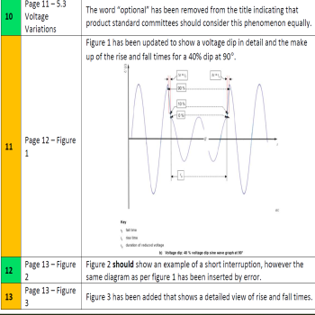
The word “optional” has been removed from the title, indicating that product standard committees should consider this phenomenon equally. |
|
|
11 |
Page 12 – Figure 1 |
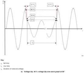
Figure 1 has been updated to show a voltage dip in detail and the make up of the rise and fall times for a 40% dip at 90°.
|
e.g. for Test laboratory: Review Calibration Certificate / Confirm method with Calibration Laboratory if necessary
e.g. for Calibration laboratory review method, consider any clarification in procedure. Update reference standard on certificate template |
|
12 |
Page 13 – Figure 2 |
Figure 2 should show an example of a short interruption. However, the same diagram as per figure 1 has been inserted by error. |
|
|
13 |
Page 13 – Figure 3 |
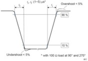
Figure 3 has been added, which shows a detailed view of rising and fall times. |
e.g. for Test laboratory: Review |
|
No. |
Section Reference |
Change |
Action Taken Blank is none or N/A |
|
|
|
|
Calibration Certificate / Confirm method with Calibration Laboratory if necessary
e.g. for Calibration laboratory review method, consider any clarification in procedure. Update reference standard on certificate template |
|
14 |
Page 14 – Figure 4 (formatting) |
The voltage verification diagram now becomes figure 4 |
|
|
15 |
Page 15 – 6.1.2 Characteristics of the Generator (formatting) |
The general preamble under section 6.1 has now been given a section number 6.1.1. as a result, numbering in this section all increments. |
|
|
16 |
Page 15 – 6.1.2 Characteristics of the generator |
The new version of the standard removes an example of what the impedance should be during voltage transitions. It now just states “should be low” rather than “0.4 + j0.25 ?”. In essence, the voltage transition impedance is now not defined in the standard. “should be low” is rather ambiguous. Existing generator impedance would be acceptable. |
|
|
17 |
Page 16 – 6.1.3 Verification of the characteristics of the voltage dips, short interruptions generators |
The following paragraph has been added, which gives greater versatility for calibration/verification of the generator for a dip to 40% nominal voltage.
“For output voltages of 40% of the nominal value, it is acceptable to verify the load regulation requirements either at 200 V to 240 V nominal voltage or at 100 V to 120 V nominal voltage”. |
|
|
18 |
Page 16 – 6.1.3 Verification of the characteristics of the voltage dips, short interruptions generators |
Reference to Annex D has been added to this section that gives detailed information on rise/fall times and inrush current capability. Annex D was in the previous version of the standard and there is no change to this Annex. |
|
|
19 |
Page 17 – 8 Test Procedures (Formatting) |
The general preamble under section 8 has now been given a section number 8.1. as a result, numbering in this section all increments. |
|
|
20 |
Page 18 – 8.3.2 Voltage Dips and Interruptions Test (Formatting) |
Figures 4a and 4b now become 5a and 5b due to previous figure additions. References in this section change to accommodate this. The figures themselves remain unchanged. |
|
Additional Supporting Information:
The following information specific to this update is provided as generic guidance. The test/calibration laboratory should review and tailor this guidance as appropriate for the quality system they operate under.
The following points address the Main headings applicable to ISO 17025:2017 normally requiring comment for an extension to scope:
T is used to denote a Test Laboratory
C is used to denote a Calibration Laboratory
Staff Training: (6.2)
T - Staff self-train on changes for reference.
C - Staff should be briefed on the meaning and intent of the changes.
Facilities and environment: (6.3)
No changes from the previous version
Test Equipment / Traceability: (6.4, 6.5)
T - The test laboratory should ensure that the calibration of rise and fall times within the standard has been carried out between the 10% and 90% points of the transition. If not, an evaluation should be carried out on the reported measurement from the current calibration certificate to establish on-going compliance with the requirement.
Review of requests, tenders, and contracts: (7.1)
No Changes required
Selection of Methods (Supporting procedures): (7.2)
T - No changes are required to existing test procedures as a result of this update.
C - Calibration laboratories should update their procedures to cover the measurement of rise and fall times in line with the new guidance showing measurement points between 10% and 90% of the transition. The diagram showing this measurement superimposed on the mains sine wave should be ideally added to the calibration procedure for additional guidance to the calibration engineer.
Measurement Uncertainty: (7.6)
No changes are required to existing measurement uncertainty budgets as a result of this update.
Ensuring the validity of results: (7.7)
No changes to the checks and validations required
Reporting of results: (7.8)
T - Change reference on Test report Master to identify new standard EN IEC 61000-4-11:2020
C – Change reference on calibration certificate Master to identify new standard EN IEC 61000-4-11:2020
Click here to see all of our articles.