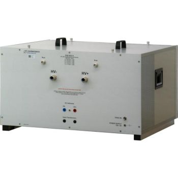
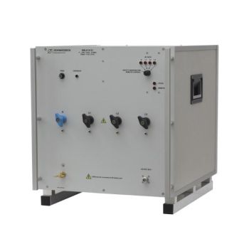
BNB 8652 B HV Line Stabilization Network
- Battery impedance network
- High Voltage - 1000VDC
- 100 Amp continuois current
- Per ISO 21498-2: 2021-03

Data Sheet
SPECIFICATIONS
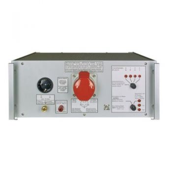
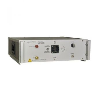
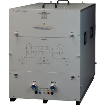
BNB 8652 B HV Line Stabilization Network (LISN)A LISN, here implemented as a battery impedance network, shall supply electric power to the device under test and provide a standardized impedance. It has been developed for automotive tests e.g. to fulfill the requirements of ISO 21498- 2: 2021-03, MBN 11123: 2021-08, (VW 80300: 2021-02), “VOLVO Impedance Stabilization Network (VISN)”, and "TVB ELECTRICAL QUALITY AND EMC REQUIREMENTS". Due to the very strict specifications regarding the tolerance for the absolute impedance in VW 80300: 2021-02 (+/-10%) and the physically achievable measurement uncertainty for resistance measurements in the milliohm range, a few values approach the limit line (uncertain), touch the limit line, or even exceed it (fail). This only affects a few values, but is unavoidable, which is why compliance with this standard is indicated in parentheses ().
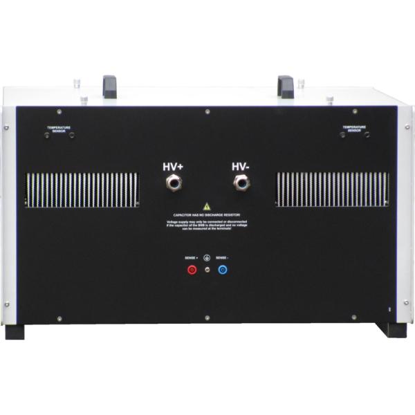
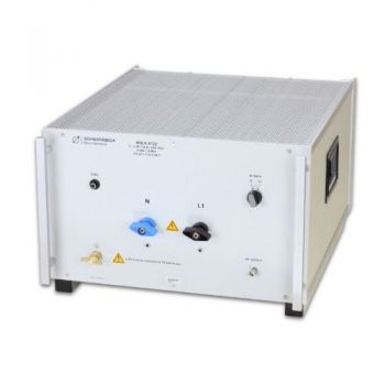
The BNB 8652 B is constructed symmetrically with two paths, HV+ and HV-. The built-in components have no specific polarity, especially the capacitors have no polarity. The paths are isolated from the housing. A foil capacitor with very low equivalent series resistance (ESR) has been used.
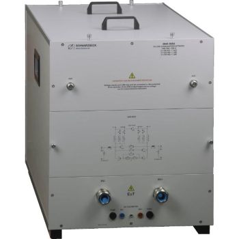
It is also possible to inject disturbance voltages. Inside the housing the BNB 8652 B can be changed over from LISN functionality to couple functionality (BNB-CN) when connecting the wires differently.
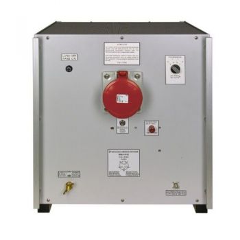
A battery can be simulated by various internal resistors. There are five possible values: 2 x 100 mΩ, 2 x 60 mΩ, 2 x 50 mΩ, 2 x 25 mΩ, and 2 x 10 mΩ (one resistance in each path). The self-inductance between the resistance connections on the EUT side is not more than 0.5 μH.
Hazard warnings Only qualified personal may use this device. Voltage supply and DuT may only be connected or disconnected when all components of the BNB 8652B are completely discharged and no voltage can be measured at the terminals. Disregarding this rule is life threatening! |
OTHER PRODUCTS IN THE SAME CATEGORY:
NSLK 8117, 9 kHz - 30 MHz, 250V / 10A, 50 µH, 2 Path LISN
NSLK 8126, 9 kHz - 30 MHz, 250V / 16A, 50 µH, 4 Path LISN
NSLK 8127, 9 kHz - 30 MHz, 250V / 16A, 50 µH, 2 Path LISN
NSLK 8163, 9 kHz - 30 MHz, 400V / 63A, 50 µH, 4 Path LISN
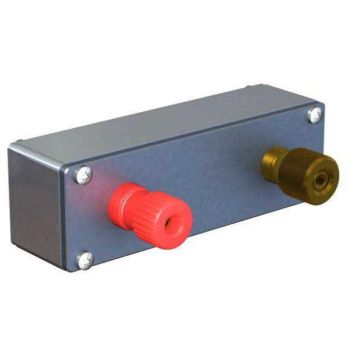
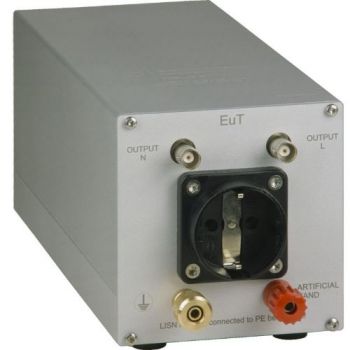
Artificial Hand
NSLK 8128, 9 kHz - 30 MHz, 250V / 32A, 50 µH, 4 Path LISN
CMDM 8700 B Common mode / Differential mode switch
BNB 8652 B HV Line Stabilization Network
BNB 8656 HV Line Stabilization Network
BNB 8654 C HV Line Stabilization Network
VTSD 9561 D, 20dB, Diode Pulse Limiter
VTSD 9561 F, 10dB, Diode Pulse Limiter
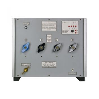
NNLK 8121, 9 kHz - 30 MHz, 400V / 100A, 50 µH, 4 Path LISN
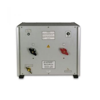
NNLK 8122, 9 kHz - 30 MHz, 1000VDC / 50A, 50 µH, 2 Path LISN
NNLK 8129, 150 kHz - 30 MHz, 400V / 200A, 50 µH, 4 Path LISN
NNLK 8129-2 HV, 150 kHz - 30 MHz, 1000V / 200A, 50 µH, 2 Path LISN
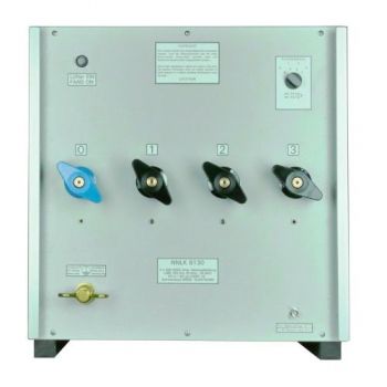
NNLK 8130, 150 kHz - 30 MHz, 400VAC/400A, 50 µH, 4 Path LISN
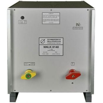
NNLK 8140, 150 kHz - 30 MHz, 1000V/800A, 50 µH, Single Path LISN
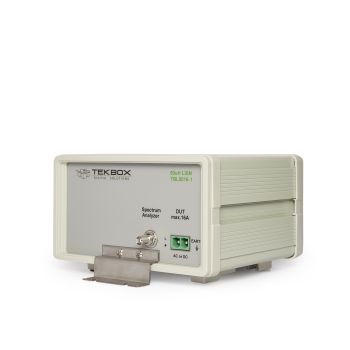
TBL5016-1 50uH 16A Line Impedance Stabilization Network LISN

