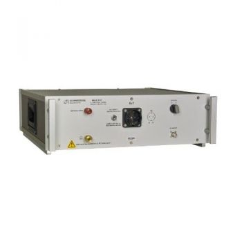
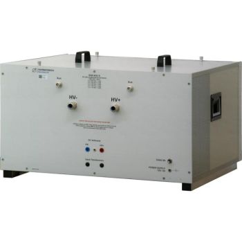
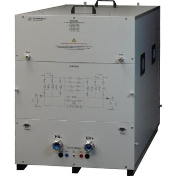
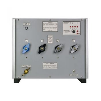
NNLK 8130, 150 kHz - 30 MHz, 400VAC/400A, 50 µH, 4 Path LISN
- High Current 4 path LISN (3-Phase)
- Line Impedance Stabilisation Network
- 150 kHz to 30 MHz
- 400/700VAC, 630 VDC, 400 A
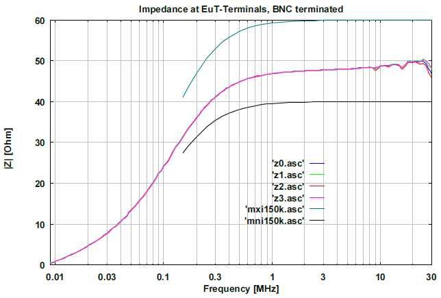
- 50 µH || 50 Ω (+/- 20 %)
- CISPR 16-1-2
PARTNER:
MARKETS:
CATEGORIES:
TEST STANDARDS:

Data Sheet
SPECIFICATIONS
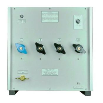
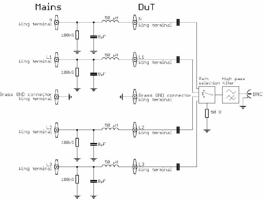
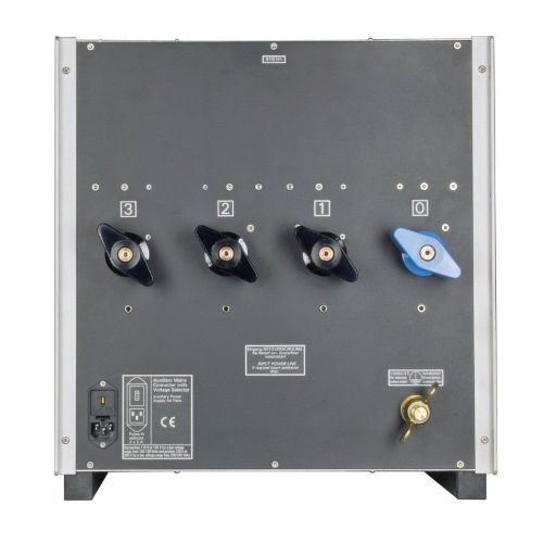
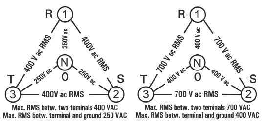
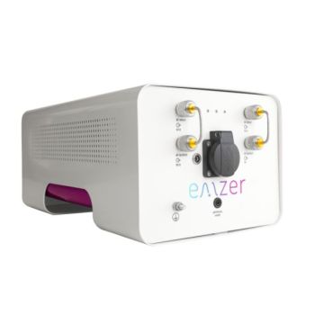
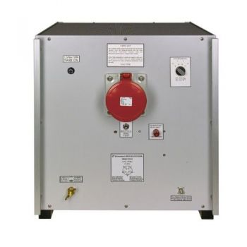
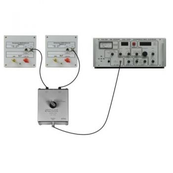
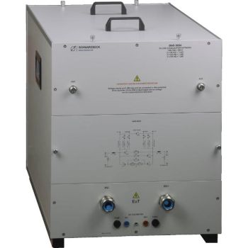
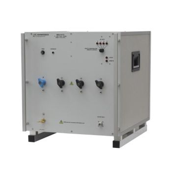
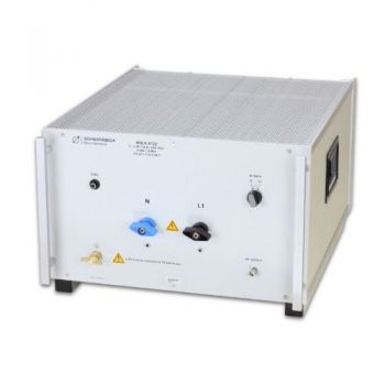
NNLK 8130, 150 kHz - 30 MHz, 400VAC (L-N) / 400A, 50 µH, 4 Path LISNThe 4 path high current Line Impedance Stabilisation Network (LISN, AMN) NNLK 8140 mainly serves to measure disturbance voltage in band B from 150 kHz to 30 MHz. It is designed to withstand very high currents and voltages. So far voltage probes had to be used for high currents and high voltages. However, voltage probes do not provide a standard impedance to the device under test so a voltage probe measurement has reduced reproducibility. The NNLK 8130 providing a continuous current capability of 400 A solves this problem. Before putting the NNLK 8130 into operation it must be connected to the earth potential. The green/yellow wing terminals at the front and back sides have to be used for this purpose. During a conducted disturbance voltage measurement all paths of the device under test should be connected to NNLK 8130 each to provide the correct impedance to each path. One path at a time is connected to the EMI receiver using a coaxial cable with a BNC plug. All other BNC connectors of the NNLKs which are not being measured at the time must be terminated using high power BNC 50 Ω termination resistors. We recommend using termination resistors that can dissipate at least 10 watts or preferable 50 watts. The exact test set up is described in CISPR 16-2-1. The impedance of the NNLK 8130 is compliant to CISPR 16-1-2 with 50 µH || 50 Ω. The LISN provides power to the DuT with a very low voltage drop. It can be used for DC, AC, or three-phase rotary current.
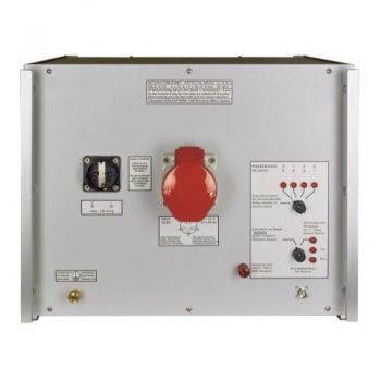
Options: Option RC for LISN: Remote Control with built-in power supply. LISN can be controlled by R&S or Schwarzbeck code, including remote control cable for your receiver type (Please specify your receiver type!). LISN can be selected from the R&S receiver menu or in the EMC32 software like an R&S LISN. No programming of the user interfaces necessary. Functions: path selection and PE grounded or via choke.
The temperature monitor module which is optionally available for the NNLK LISN warns the user visually and acoustically when the temperature gets too high. It controls the fans of the LISN temperature-dependent, too, and thus prevents overheating. If a critical temperature is reached the temperature control module indicates this optically and acoustically.
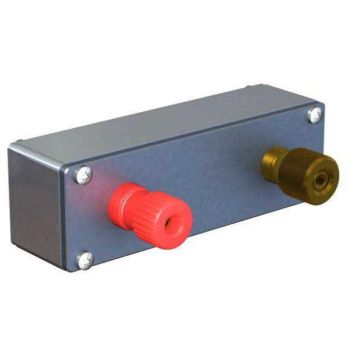
The NNLK 8130 is equipped with a high pass filter but not with a pulse limiter. The EMI receiver should therefore be protected against overload. The VTSD 9561 F is an external pulse limiter that is suitable for this purpose. If the amplitude of the disturbance voltage exceeds values which could be dangerous for the EMI receiver input the pulse limiter will cut these pulses. This causes additional spectral lines in the frequency domain (“phantom spectral lines”). The excess-pulse-energy illuminates an electric bulb. If the bulb glows or lights up the measurement is not valid because of the phantom spectral lines. In such a case more attenuation must be used at the measuring port of the LISN. An external attenuator must be dimensioned sufficiently especially under the presence of strong harmonics of the mains frequency |


OTHER PRODUCTS IN THE SAME CATEGORY:
NSLK 8117, 9 kHz - 30 MHz, 250V / 10A, 50 µH, 2 Path LISN
NSLK 8126, 9 kHz - 30 MHz, 250V / 16A, 50 µH, 4 Path LISN
NSLK 8127, 9 kHz - 30 MHz, 250V / 16A, 50 µH, 2 Path LISN
NSLK 8163, 9 kHz - 30 MHz, 400V / 63A, 50 µH, 4 Path LISN
Artificial Hand
NSLK 8128, 9 kHz - 30 MHz, 250V / 32A, 50 µH, 4 Path LISN
CMDM 8700 B Common mode / Differential mode switch
BNB 8652 B HV Line Stabilization Network
BNB 8656 HV Line Stabilization Network
BNB 8654 C HV Line Stabilization Network
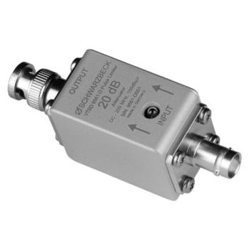
VTSD 9561 D, 20dB, Diode Pulse Limiter
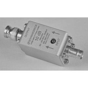
VTSD 9561 F, 10dB, Diode Pulse Limiter
NNLK 8121, 9 kHz - 30 MHz, 400V / 100A, 50 µH, 4 Path LISN
NNLK 8122, 9 kHz - 30 MHz, 1000VDC / 50A, 50 µH, 2 Path LISN
NNLK 8129, 150 kHz - 30 MHz, 400V / 200A, 50 µH, 4 Path LISN
NNLK 8129-2 HV, 150 kHz - 30 MHz, 1000V / 200A, 50 µH, 2 Path LISN
NNLK 8130, 150 kHz - 30 MHz, 400VAC/400A, 50 µH, 4 Path LISN
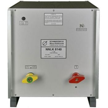
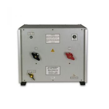
NNLK 8140, 150 kHz - 30 MHz, 1000V/800A, 50 µH, Single Path LISN
TBL5016-1 50uH 16A Line Impedance Stabilization Network LISN

