What are common attenuators values for EMC and RF testing?
What are common attenuators values for EMC and RF testing?
Attenuators come in almost any value you can imagine, but some common values are used and more readily available. Below is a review of commonly used attenuators and why they are good to have in your EMC/RF tool kit. If you always are working in the logarithmic “dB” measurement scale and never need to convert to linear measurements, then the selection of your attenuators is not as critical. But there will be times when you need to troubleshoot or verify a setup to which knowing these values becomes more important. Test standards and equipment specifications all come in different formats and units, some linear and some logarithmic (dB). Moving back and forth from log to linear is an important skill to verify setups.
It can be understandable why 10dB is typical and 20 dB for the same reason it’s a nice round number, but there is more to it. And then there are 3dB and 6 dB attenuators. Why not 5dB or 9dB?
10dB Attenuator: In power 10dB up or down on the scale is a 10x factor. 1 watt signal (30 dBm) with a 10dB attenuator is now 0.1 watts (20 dBm). It is an easy math equation in your head. Just move the decimal one spot. 10dB is not a “clean” calculation for voltage or current so it is not advisable to use it for these measurements
20dB Attenuator: In Voltage or Current, 20dB up or down on the scale is a 10x factor. 1 volt (120dBµV) signal with a 20dB attenuator is now 0.1 Volts (100dBµV). It is an easy math equation in your head. Just move the decimal 1 spot. For power, 20dB would be 100x factor; move the decimal 2 times.
What if the above instances are just too much attenuation for your needs:
3dB Attenuator: In power, the reading would be ½ the measurement. For example, a 1-watt signal attenuated by 3dB becomes 0.5-watts. 3dB is not a “clean” calculation for voltage, or current so it is not advisable to use it for these measurements
6dB Attenuator: In voltage or Current, the reading would be ½ the measurement. For example, a 1-volt signal attenuated by 6dB becomes 0.5-volts. For power, it would be a 4x factor, not as ideal a tool for a simple equation but within reason.
For instances where more attenuation is needed:
30 & 40 dB Attenuators and above: Used when a very large signal needs to be reduced to bring it down to be measured and to protect the measurement instruments. With a complete attenuator kit of 3, 6, 10, 20, 30, 40 dB, you have a very versatile solution to meet any application that may arise. Higher attenuation than 40dB is possible with the kit. The attenuators can be connected together to add their attenuation together to reach 100dB attenuation.
Example: 30+20=50, 40+20=60, 40+30=70, 40+30+10=80, 40+30+20=90, 40+30+20+10=100
Linear Unit Factors
|
|
Power (dBm) |
Voltage (dBµV) or Current (dBµA) |
||
|
|
Gain |
Attenuation |
Gain |
Attenuation |
|
3dB |
2x |
1/2 |
1.408 |
0.71 |
|
6dB |
4x |
1/4 |
2x |
1/2 |
|
10dB |
10x |
0.1 |
3.125x |
0.32 |
|
20dB |
100x |
0.01 |
10x |
0.1 |
|
30dB |
1000x |
0.001 |
31.625 |
0.03162 |
|
40dB |
10000x |
0.0001 |
100x |
0.01 |
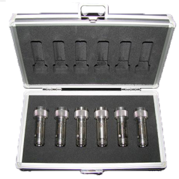
DGA 9552 N, 5 watts, 18GHz, 3, 6, 10, 20, 30, & 40dB
A bidirectional attenuator, i.e., the attenuation and power capability specification, is valid for both directions. There is a large variety of applications for this attenuator: The measuring range of a spectrum analyzer can be increased. Any kind of meter can be protected against overload; it can be used to control the linearity of a meter reading. It can minimize measurement uncertainty caused by mismatched impedances. During an EMI receiver calibration, an attenuator directly at the pulse generator output is inevitable.
Every DGA 9552 N is delivered with an individual calibration of the attenuation. Calibration data of the VSWR is available on request. Sold individually or as a kit.
|
Specification |
DGA 9552 N |
|
Frequency Range: |
DC ... 18 GHz |
|
Impedance: |
50 Ohm |
|
Connectors: |
Precision type N, acc. to MIL-STD-348 |
|
Attenuation: |
3, 6, 10, 20, 30, 40 dB |
|
Length: |
56.4 mm |
|
Max. Power:
|
5 W / 25 °C, 4 W / 45 °C, 3 W / 65 °C, 1 W / 105 °C |
|
VSWR:
|
less than 1.15 (DC – 4 GHz) |
|
Temperature Range: |
-55 ... 105 °C |
|
Standard: |
MIL-DTL-3933 |
|
Body: |
Stainless steel |
|