EMC Emissions Testing and Pre-Compliance Tools
EMC Emissions Testing and Pre-Compliance Tools
By Jason H Smith
Engineer & President of Absolute EMC llc
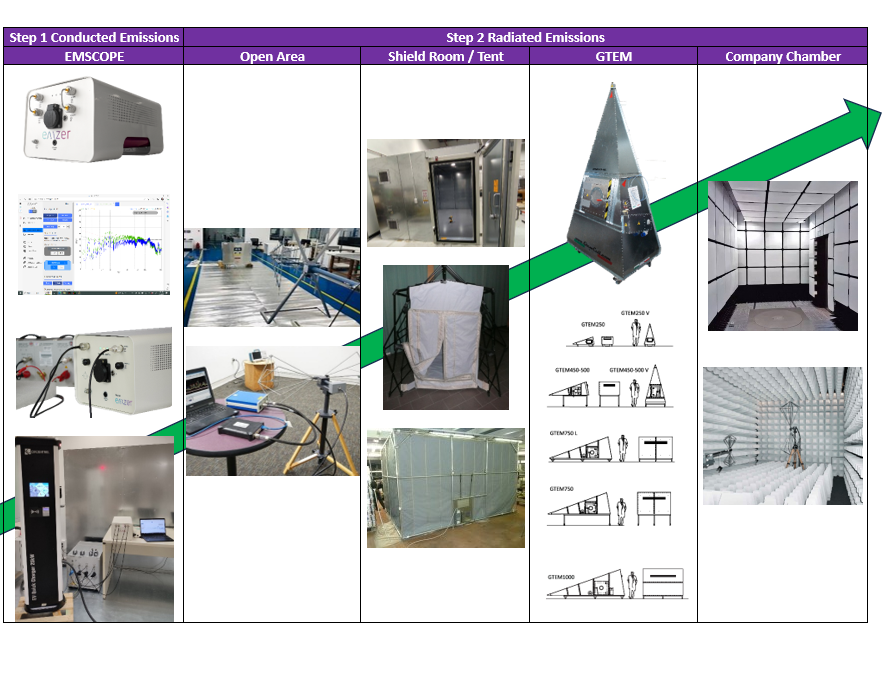
Electromagnetic Compatibility (EMC) testing ensures electronic devices comply with regulatory standards and operate without interference in their intended environments. EMC emissions testing focuses on measuring and controlling electromagnetic emissions from devices to prevent interference with other equipment or systems. Pre-compliance testing, using tools such as EMSCOPE, current probes, shield rooms EMI Tents, GTEMs, and compact chambers, is vital in identifying potential issues early in the development process, saving time and resources. This article will delve into the methodologies, tools, and setups involved in EMC emissions testing and the benefits and shortcomings of various approaches.
Embarking on EMC product development with a conducted emissions setup is a prudent and cost-effective initial step. Conducted emissions can pose challenges during EMC lab testing. By integrating EMC considerations into the design phase, you can potentially resolve many radiated emissions issues, leading to significant cost savings. A well-executed conducted emission design can be a game-changer in your product's EMC compliance journey.
Conducted Emissions Testing with Pre-Compliance Tools
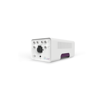
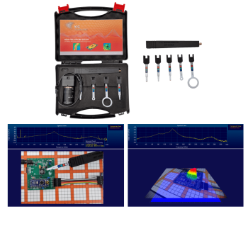
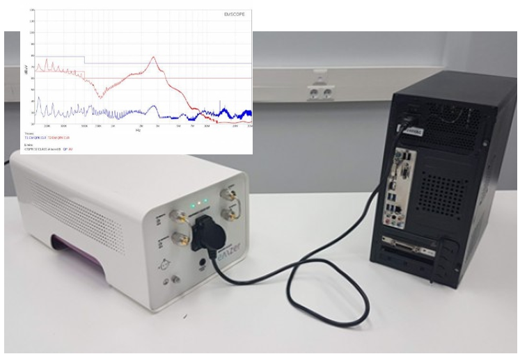
Conducted emissions refer to electromagnetic disturbances transmitted through conducted means, such as power and signal cables. Pre-compliance testing involves using tools like EMSCOPE, LISNs, and current probes to measure these emissions. EMSCOPE is an EMI receiver specifically designed for EMC testing, capable of analyzing emissions across a wide frequency range. The EMSCOPE includes a built-in LISN for commercial and MIL-STD testing but can easily be connected to external LISNs for other applications. The EMSCOPE's real-time measurement capabilities are its standout feature, significantly reducing evaluation testing time and the knowledge needed. Product design engineers can plug in prototype products and get results within seconds. The real-time measurement of all test lines at the same time every second in Peak, QP, and AVG is the only device that allows this. Find out a failure and evaluate the type of failure of common mode or differential mode to produce a quick and easy filter fix/design.
 Additionally, other measurement accessories can be connected to the EMSCOPE to take the evaluation testing further. Current probes and nearfield probes measure conducted emissions. Current probes clamp around cables where a LISN might not be acceptable, allowing direct measurement of the RF levels. Nearfield probes probe connectors and PCB circuit boards to pinpoint where the emissions may be coming from.
Setup:
EMSCOPE Setup: Connect EMSCOPE to the device under test (DUT) and ensure proper calibration. Place the DUT in an EMC test chamber or an open area away from other electronic equipment to minimize external interference. The EMSCOPE with LISN will produce measurements directly correlated to what a full compliance test lab will measure.
Current Probe Setup: Clamp the current probe around the DUT's power or signal cables. Connect the probe's output to the spectrum analyzer or EMSCOPE's input for analysis.
Benefits:
Early Detection of Issues: Pre-compliance testing allows for the early identification of potential EMC issues, reducing the risk of costly redesigns later in the development process.
Cost-Effective: The EMSCOPE is one of the most cost-effective products available. Pre-compliance tools help save time and resources by identifying problems before formal compliance testing, avoiding expensive test lab fees.
Quick Iterative Testing: With pre-compliance setups, engineers can quickly iterate designs and test modifications, accelerating product development.
Shortcomings:
Area for setup: The setup should mimic a full compliance setup to produce more accurate results. A floor and vertical ground plane will be needed. If external interference from the building’s power or environment is an issue, power filtering or test shielding may be required, which adds some complexity to the setup. Testing without ground planes is possible.
Reproducibility: Current probes and near-field probes are good for finding frequencies but are less reliable than the LISN setup for level reproducibility.
Radiated Emissions Testing in Open Office Environments
 The next step in evaluating your product during the engineering phase is radiated emissions testing. This testing is much more complex and involves measuring electromagnetic emissions emitted by a device into free space. It can become quite costly and complex, which scares some people away from having pre-compliance test tools. However, many less expensive options are available to fit any budget. One step is using low-cost TEM Cells or Open TEM Cells with a shielded bag/tent to evaluate circuit boards and small EUT/DUTs. However, these options are size-limited and frequency-limited. Only fitting some applications. Testing in an open office environment presents advantages and challenges to evaluating a larger EUT/DUT. To test in the open your need:
- Spectrum analyzer with EMI option
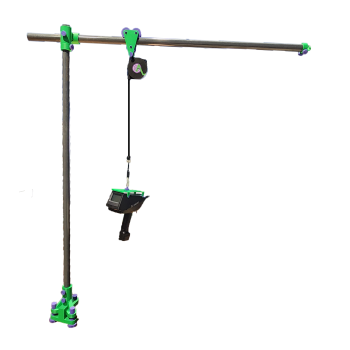
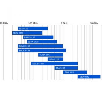
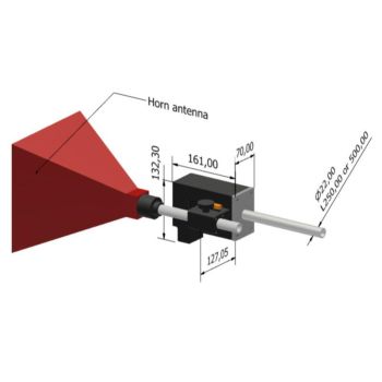
- Emissions antenna/s, w/tripod
- Low-loss Coax cable
- Pre-amplifier
- Optional Software (most Spectrum analyzers can apply antenna factors and run scans without software)
Setup:
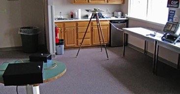
Open Office Setup: Place the DUT on a non-metallic table in the center of the office space. Ensure no large metal objects nearby could reflect or interfere with emissions. The more open the area, the better. Testing outside in the parking lot or an open lawn area may also be beneficial.
Distance Measurement: To ensure accurate measurements, maintain a consistent distance between the measuring antenna and the DUT. If following the standard, this can be 3m or even 10m. Shortening the distance for open areas and applying a dB correction is best. 10dB is used when designed at 3m instead of 10m.
Benefits:
Cost Savings: This setup in the open has a low startup cost. Utilizing existing office space for testing eliminates the need for specialized EMC chambers, reducing testing costs.
Setup: This setup more closely mimics the real lab setup to achieve the proper test distance. It is good for evaluating a limited number of defined frequencies.
Shortcomings:
Interference: Radiated emissions testing in an open environment is susceptible to interference from external sources such as nearby electronics, Wi-Fi networks, and radio transmissions. Evaluating the whole frequency range is normally impossible as ambient levels will make it difficult.
Inconsistent Results: Setup differences from test to test will result in lower reproducibility.
Not Ideal Setup: the EUT/DUT is not on a turntable, and the antenna is not on a mast to perform a full evaluation.
Closing the distance of the antenna to the EUT/DUT will help elevate measured levels higher than Interference levels and close the measurement angle to gather more DUT/EUT emissions.
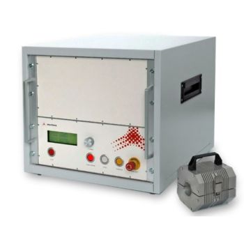
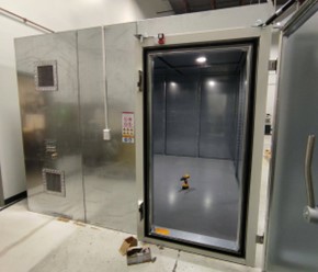
Improving Testing with EMI Shielding
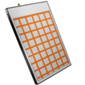
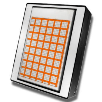
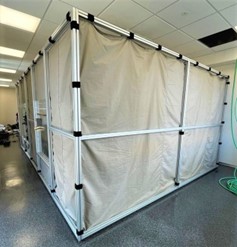
One of the most challenging problems with testing in the open is interference or dealing with ambient levels. To eliminate the interference, the testing is isolated from the outside world. This is done by using a shielded room. A shielded room refers to a metal box with a shielding effectiveness (SE) of about 80-100dB, which is the level at which it attenuates the signals from outside to inside or vice versa. An alternative is a shielded Tent. This uses a shielded fabric instead of metal walls to allow an SE of about 60-85dB; depending on design, this can be more. Differences:
|
Shield room |
EMI Tent |
| More permanent (installation team) | Less permanent, can be taken down and moved |
| Higher cost | Lower cost |
| More consistent results | Walls move, and RF bounces. |
| Higher SE attenuation | lower SE attenuation |
| Recommended |
Shield Room or EMI Tent Setup:
The setup is similar to open-area testing, except now inside a shielded enclosure. Due to the room size, the test distance will be what is allowed. The antenna needs to maintain safe clearance from walls, ceilings, and floors.
Benefits: EMI shielding enclosures or tents provide a controlled environment, minimize external interference, and ensure measurements are from the EUT/DUT. They are additionally useful for conducted emissions testing.
Shortcomings: EUT's Radiated Emissions will bounce and reflect off internal walls. Getting repeatable results is not easy. Product position and layout are critical; very small changes result in very different results. Performing Radiated immunity testing in a shielded room will not produce repeatable results.
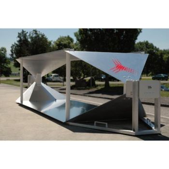
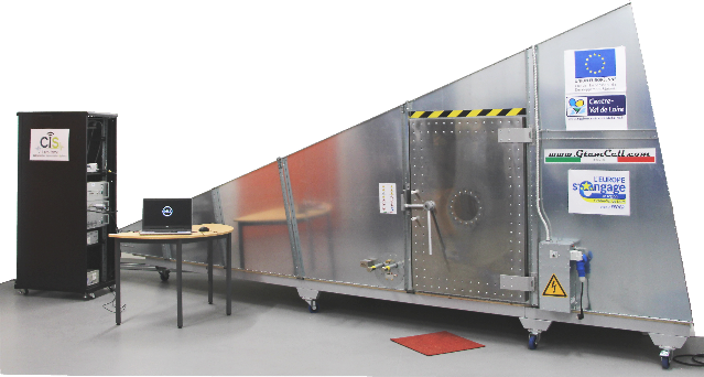
Further improving the testing with a GTEM
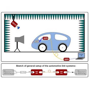
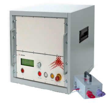
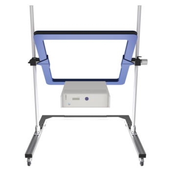
GTEM (Gigahertz Transverse Electromagnetic) cells are an ideal compromise between a shielded room and a compact anechoic chamber. Depending on the size of the EUT/DUT, different GTEMs are available. A GTEM measures (or produces) fields from a metal plate called a septum. It is a chamber and antenna in one. IEC 61000-4-20 is an international standard listing the requirements and use of the GTEM. Because the GTEM is recognized, it is a more accepted pre-compliance tool. This unit solves all of the shortcomings given earlier. Results are reproducible; results can be correlated to a full compliance setup, SE of 80dB +, which is suitable for both radiated emissions and immunity.
GTEM Cell Setup:
Benefits: GTEM cells offer a standardized and controlled testing environment, improving repeatability and accuracy of measurements. Correlation to a full compliance chamber can be achieved by using a reference for comparison, such as a comb generator.
Shortcomings: One of the only shortcomings is that if the EUT/DUT is very large, a GTEM size will become large, taking up more lab/building space and increasing cost, bringing it closer to what a compact Anechoic chamber will be in cost.
NOTE: Other test cells on the market integrate an antenna and cell into a compact system. A manufacturer has uniquely developed these systems. You will have to investigate them to see if they offer advantages. The GTEM is a known design built to an international standard, and it should be more universally accepted and understood.
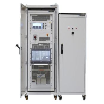
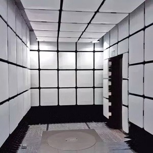
Compact EMC Chamber for Pre-Compliance Testing
Compact EMC chambers offer an ideal solution for comprehensive pre-compliance testing with improved repeatability. This solution is recommended if you have the lab space and budget. It takes the next step to be closer to a fully compliant setup while still having cost savings over being fully compliant.
Benefits:
Controlled Environment: Compact EMC chambers provide a controlled and shielded testing environment, minimizing external interference and ensuring repeatable results.
Versatility: These chambers are designed to accommodate a variety of device sizes and configurations, allowing for flexible testing setups. It can be expanded for Radiated Immunity testing as well.
Shortcomings:
Space Limitations: Chambers require a good amount of space to be installed. You will need to have this real estate available.
Resource Requirements: Setting up and maintaining a compact EMC chamber requires resources and expertise, which may pose challenges for smaller organizations with limited budgets or technical capabilities.
In conclusion, EMC emissions testing, particularly in pre-compliance scenarios, involves a careful balance of cost, accuracy, and repeatability. Starting with an easy-conducted emissions setup is your first step. While pre-compliance tools for radiated emissions and open environment testing offer advantages such as cost savings, they may lack the accuracy and consistency required for your engineering testing needs. EMI shielding, GTEM cells, and compact EMC chambers address these shortcomings by providing controlled environments for more accurate and repeatable testing, albeit at a higher cost and resource investment. Ultimately, the choice of testing methodology depends on the specific requirements, budget, and resources available to the organization conducting the tests.