COUPLING TRAFO IMPLEMENTATION VERSUS BOLAB 4 QUADRANT AMPLIFIER IN SERIES
COUPLING TRAFO IMPLEMENTATION VERSUS BOLAB 4 QUADRANT AMPLIFIER IN SERIES FOR HIGH VOLTAGE TESTS FOR ELECTRIC VEHICLES
 |
The biggest challenges in testing according to:
| LV 123 | VW 80300 | VW 80303 | NBN LV 123 |
| ISO 21498-2 | |||
| Nissan / Renault 36-00-811 | Many other standards | ||
DIFFERENCES BETWEEN LV 123, VW 80300 AND ISO 21498-2 FOR IMMUNITY TO VOLTAGE RIPPLE
| LV 123 | VW 80300 | ISO 21498-2 | |
| Robustness against Voltage Ripple | 10.4.6 | EHV-09 | 6.6 |
| Frequency range | 15 Hz … 20 kHz | 10 Hz … 150 kHz | 10 Hz … 150 kHz |
| Max. Amplitude | 15 Vpk | 16 Vpk | Must be agreed between customer and supplier |
| Robustness against Load Dump | 10.4.9 | EHV-10 | 6.11 |
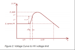
| Load dump all the way to HV voltage limit | 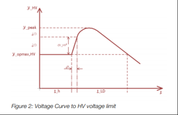 |
 |
 |
| HV-Slope ΔVHV/Δt: | 250 V/ms | 250 V/ms | 250 V/ms |
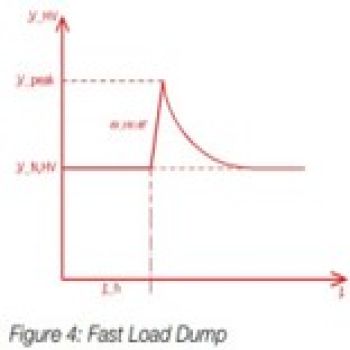
| Load dump with rapid rate of change | No Test | EHV-10 | No Test |
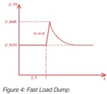 |
|||
| HV Slope | 3000 V/ms | ||
| Peak Voltage | Upk = UN,HV + 20 V | ||
| Resulting Speed | dU/dt pk= 20 V / 7µs | ||
SETUP WITH COUPLING TRANSFORMERS AND RESULTING PROBLEMS
- Available for different frequency ranges and currents (50 A / 100 A)

- Setup must be changed to exchange coupling transformers
→ test must be interrupted to run full frequency range - At low frequencies, as required in LV 123 for simple DUTs with low capacitive components and low currents, this solution can work well
- Coupling transformers go into saturation at the lowest frequencies through their high inductivity
→ Low-frequency range must be performed only with a power supply - High frequencies up to 150 kHz are difficult or impossible (LV 80300, ISO 21498-2) under real DUT/load conditions
- Many OEMs and standards are required to run the entire frequency range without interruption, no stop or modification of setup
COUPLING TRANSFORMER CHARACTERISTICS FOR LOW-FREQUENCY RANGE AND ANOTHER FOR HIGH-FREQUENCY RANGE – WITH OHMIC LOADS
 |
 |
COUPLING TRANSFORMER CHARACTERISTICS WITH OHMIC LOADS
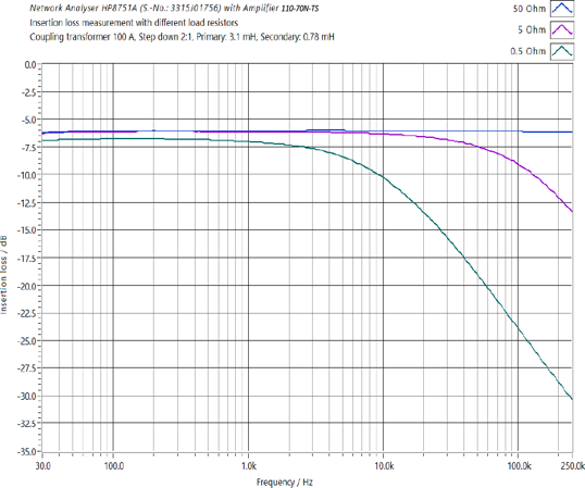
- TRANSFORMER FOR LOWER FREQUENCY RANGE TRANSFORMER WITH 100 A, EXAMPLE RIPPLE 20 VPP
| With 50 Ohm load at 10 Vp | →I = 0,2 A | →voltage at DUT stays constant without drop at higher frequencies |
| With 5 Ohm load at 10 Vp | →I = 2 A | →voltage at DUT drops at 10 kHz, up to 100 kHz significant |
| With 0,5 Ohm load at 10 Vp | →I =20 A | →voltage at DUT drops after 1 kHz dramatically, although a 100 A transformer is used |
Result:
The low-frequency transformer characteristic shows that only for low current and low frequency can the transformer be used even with ohmic loads.
COUPLING TRANSFORMER CHARACTERISTICS WITH OHMIC LOADS
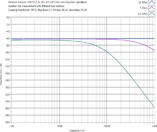
- TRANSFORMER FOR HIGHER FREQUENCY RANGE TRANSFORMER WITH 100 A, EXAMPLE RIPPLE 20 VPP
| With 50 Ohm load at 10 Vp | →I = 0,2 A | →voltage at DUT stays constant without drop at higher frequencies |
| With 5 Ohm load at 10 Vp | →I = 2 A | →voltage at DUT drops after 200 kHz |
| With 0,5 Ohm load at 10 Vp | →I =20 A | →voltage at DUT drops after 50 kHz dramatically, although a 100 A transformer is used |
Result:
The high-frequency transformer characteristic shows that only for low current can it be used even with ohmic loads.
PROBLEMS WITH COUPLING TRANSFORMERS
- What if a DUT consumes 200 A, 300A, or more ripple current?
- Several coupling transformers (e.g. 100 A transformers) can be put in parallel or assembled in one housing
- But: Each coupling transformer requires its own power amplifier
- → This requires an enormous effort to implement coupling transformers with different frequency ranges at high current applications
- → The quality result is not satisfactory despite the disproportionately large effort
- In most cases, DUTs have considerable input capacitance à Cannot be handled by a transformer, only ohmic loads
- Limits of technical feasibility are quickly reached
- Expensive bad investments are and were made because the physical and electro-technical limits were not conscious or one is not pointed out at all to these limitations.
- Only periodic sinusoidal signals can be coupled in
- Transient pulses such as EHV-10 "Load Dump with a rapid rate of change" from the VW 80300 → impossible
- Many standards require closed-loop procedures, in which the voltage must be readjusted up to certain levels to maintain the voltage at the DUT
- The dramatic voltage losses from the coupled voltage to the applied ripple voltage at the DUT cannot be compensated as losses inside the transformers are too dramatic
- The reason is the insufficient output voltage of the amplifier at the required current demands, which results in a limited or often insufficient readjustment possibility in the amplifier
BOLAB‘S SOLUTION:
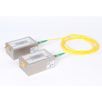
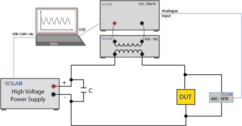
BOLAB AC AMPLIFIER IN SERIES TO THE HV-DC VOLTAGE SOURCE
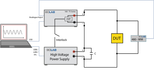 In this case, an AC 4-quadrant amplifier system is connected in series to the HV-DC power supply
- Solves the difficulties of the coupling transformer solution out of an ideal power waveform generation
- Full frequency range without changing any setup
- The identical current flows through both the HV-DC source and the 4-quadrant amplifier
WHY ARE SUCH SOLUTIONS LESS COMMON ON THE MARKET?
- It’s too difficult to operate two completely different sources in series which actually do not fit together.
- This table shows the differences between the two supply components:
| Typical features | HV-DC power supply | 4-Quadrant amplifier |
| Design principle | Switched | Analog |
| Output voltage | 0 V … 1.000 V | -100 V … +100 V |
| Quadrants | 2 Quadrants | 4 Quadrants |
| Output capacitance | Yes | - |
| Rise / fall time | 1 ms | 1 μs |
| Power range | 15 kW … 500 kW | 500 W … 18 kW |
COMPARISON SETUP
| Coupling Network Transformers (CDN) | DC power supply + 4-Quadrant Amplifier in series |
 |
|
| LOW FREQUENCY, NO CAPACITOR IN DUT | |
 |
 |
|
→ Both the coupling transformer and the AC + DC solution full fill this task well. |
|
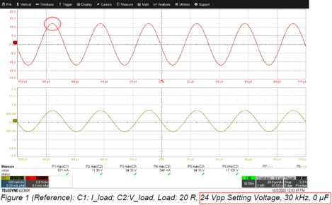
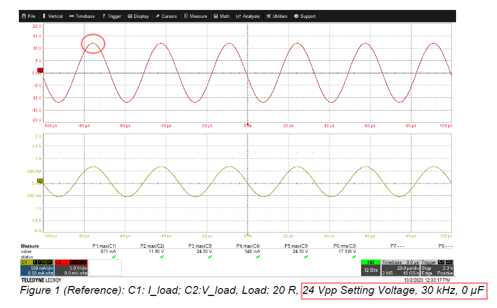
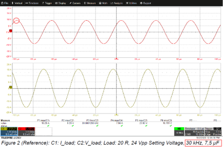
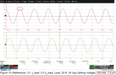
| LOW FREQUENCY, SMALL CAPACITOR IN DUT | |
 |
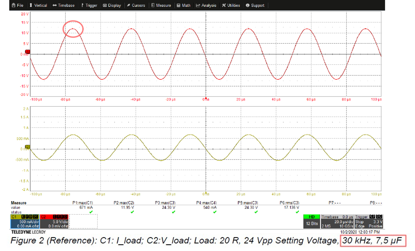 |
| ◊Voltage drop to approx. 9 Vpk ◊The voltage difference can be readjusted by increasing the transformer control voltage. |
◊ Voltage stays on 12 Vpk with DUT capacitor of 7,5 µF |
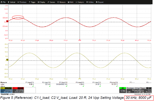
| LOW FREQUENCY, HIGH CAPACITOR IN DUT | |
 |
◊ Missing measurement, See below measurements for high frequency |
| ◊Voltage of 12 Vpk drops to 500 mVpk ◊The amplifier that is responsible for the transformer voltage thus does not have sufficient resources to compensate for these drastic voltage drops → Test fails! |
◊ No Drop in Voltage, Voltage stays on 12 Vpk |
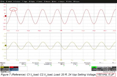
| HIGH FREQUENCY, NO CAPACITOR IN DUT | |
 |
◊ Missing measurement, See below measurements for more difficult conditions |
| ◊ Voltage drop to approx. 11 Vpk ◊ The voltage difference can be readjusted by increasing the transformer control voltage. |
◊ Voltage stays on 12 Vpk |
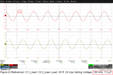
| HIGH FREQUENCY, SMALL CAPACITOR IN DUT | |
 |
 |
|
◊ Voltage drops to approx. 1,5 Vpk |
◊ Voltage stays at 12 Vpk with DUT capacitor of 7,5 µF at 150 kHz |
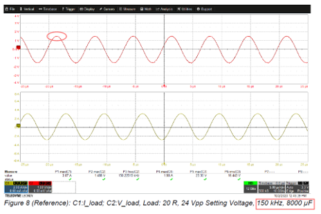
| HIGH FREQUENCY, HIGH CAPACITOR IN DUT | |
 |
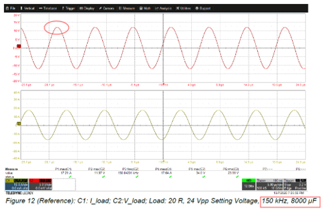 |
| ◊ Voltage drops to approx. 1,5 Vpk ◊ Amplifier, that is responsible for the transformer voltage thus does not have sufficient resources to compensate for these drastic voltage drops → Test fails! |
◊ Voltage stays on 12 Vpk even with DUT capacitor of 8000 µF at 150 kHz |
| HIGHEST FREQUENCY, SMALL CAPACITOR IN DUT | |
| only signal not seen at 250kHz → Test fails! | 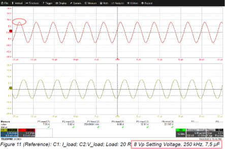 |
| ◊ Example test choosen from a requirement from an automobile manufacturer: ◊ 8 Vpk at 250 kHz → this system concept also provides sufficient reserves for even higher requirements with future perspectives |
|
SUMMARY OF COUPLING TRANSFORMER SOLUTIONS
- Datasheets in most cases, only provide information about technical data and tests under no-load operating conditions
- High frequencies are specified, but without specification of load, respectively in reference to impedance conditions
→ Neither reliable statements about resistive loads nor reactive loads are available
CONCLUSION
- The advantages of the BOLAB system solution with an HV-DC source in series with BOLAB´s amplifier systems show impressive results
- Tests according to standards can now be realized that were impossible before
- By using a powerful amplifier, both high-voltage standards such as LV 123, VW 80300, ISO 21498-2, etc. and the low-voltage standards for the 12 V, 24 V, and 48 V electrical systems such as LV 124, VW 80000, VDA 320, etc., can be carried out with the same amplifier system
- Only a few components have to be procured
- low purchase price
- low complexity of the system design
- Standards and norms appearing in the future with even higher requirements can also be implemented and carried out with this solution approach.
- Not only superimposed AC voltages can be performed with this approach, but also load dump tests can be performed.
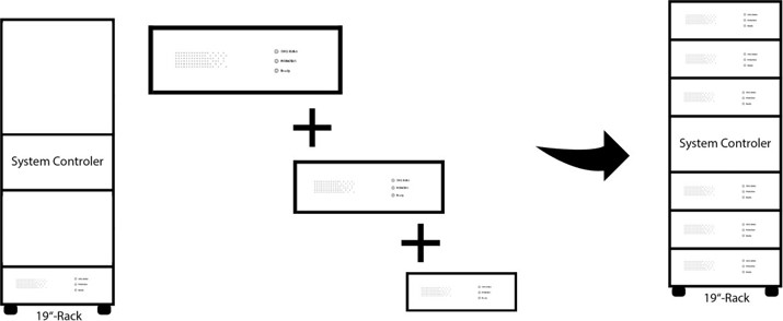
- A modular BOLAB 4-quadrant amplifier system also has the advantage that a simple upgrade with further power amplifier modules is possible at any time and thus also expands future perspectives.
- For the high voltage DC power supply part, most of all high voltage sources and manufacturers can be used; high-performance high voltage DC power supplies are part of BOLAB solutions as well.