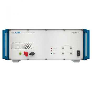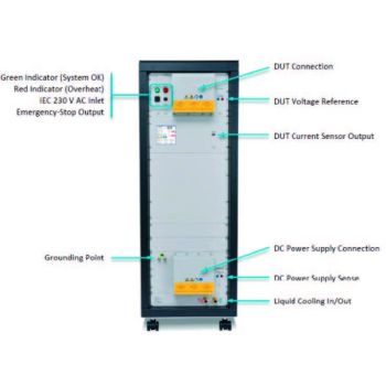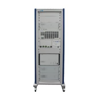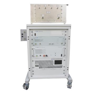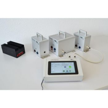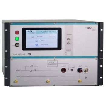
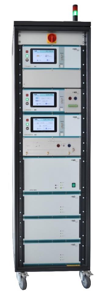
CAR SYS 14 EFT/Micro-pulse +CDN Generator
The EMC test system is designed for testing electromagnetic immunity of the electrical installation of vehicles and components against supply line transients. EMC - Test Equipment for the electrical installation of vehicles.
- Pulse #1 1-5/2000us, 600 V
- #1 1-5/1000us, 600 V
- Pulse #2a 1 / 50us, 600 V
- Pulse #3 5/100 ns, 800 V
PARTNER:
MARKETS:
TEST STANDARDS:
- FMC1278 ,
- GM W 3097 ,
- ISO 16750-2 ,
- ISO 7637-2 ,
- ISO 7637-3 ,
- SAE J 1113/2 ,
CAR - TEST - SYSTEM 14
EMC-Test Equipment for the electrical installation of vehicles
Highlights:
- Rise time variable 1- 5µs
- Vehicle voltages : 12V / 24V / 42V / 48V / 70V
- Battery current: 50A / 100A / 200A
- Electronic sense for battery voltage
- Modular and extendable
|
According to |
| ISO 7637: 2011 |
| ISO 16750: 2012 |
| ISO 21848 |
| LV 124, LV 148 |
| … various manufacturer standards |
|
Included Pulse |
Waveform |
Voltage |
Standard |
Ri |
|
Pulse 1
|
1-5/2000µs 1-5/1000µs |
600 V 600V |
ISO / SAE
|
|
| Pulse 2a | 1 / 50µs | 600 V | ISO | 2/4/10/20/30/50/90/150 W |
| Pulse 3 | 5/100 ns | 800 V | ISO | 50 W |
The EMC test system is designed for testing electromagnetic immunity of the electrical installation of vehicles and components against supply line transients.
The CAR-SYS allows, in its basic configuration generation of transient immunity test pulses, pulse #1, #2 and #3. It contains a triggerable load switch, an Ethernet interface board and an integrated fast pulse voltage divider to measure the impulse in the electrical.
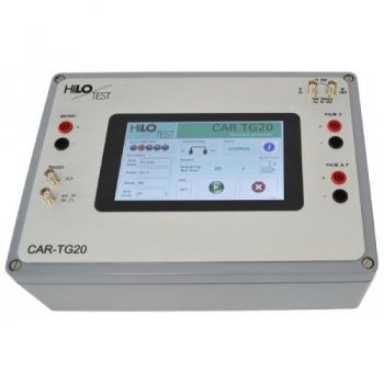
A microprocessor-controlled 7" touch screen display unit is integrated and permits easy operation of the generator. The software program CAR-remote permits the PC control of the generator via Ethernet and also allows the standardized documentation according to IEC 17025 and the evaluation of test results. The user can use the standard test routines (ISO, VG, Car manufacturer specific) or define his own test sequences. It is equipped with an Impulse Recording Function (IRF) to record definite impulses (with oscilloscope).
Furthermore, nearly all customer-specific impulse adjustments are possible by flexible software control.
The CAR-SYS excels by its compact design, simple handling, and precise reproducibility of test impulses. High-voltage switching is accomplished utilizing a maintenance-free semiconductor switch.
04/20
Optionally, it can be expanded with the electronic power supply:
Systems with HILO-TEST power amplifiers:
|
Variations |
Power amplifier |
Continuous current |
| CAR-TEST-SYSTEM SYS 14 I | PS 66-55 | 50 A |
| CAR-AWG 1200 | 40 A | |
| CAR-TEST-SYSTEM SYS 14 II | PS 66-110 | 100 A |
| CAR-AWG 3000 | 100 A | |
| CAR-TEST-SYSTEM SYS 14 III | PS 74-220 | 200 A |
| CAR-AWG 6000 | 200 A |
The Power amplifier serves as the battery supply for the DUT. It can as well create remote-controlled amplifier pulses, like pulse 2b, pulse 4, sine between, and pulse 5 (Test A and B). Up to 200A.
Comparison of the amplifier extensions:
|
Type |
PS xx-xx |
CAR-AWG |
| Description | Power supply controllable over Ethernet | Arbitrary Waveform Generator |
| Version | 66-55 66-110 74-220 | 1200 3000 6000 |
| Max. Voltage | 74V | 75V |
| Max. Current | 50A 100A 200A | 40A 100A 200A |
| Slew Rate | 10V/µs | 80V/µs |
| Bandwidth | - | DC-1MHz |
| Controllable battery voltage | Yes | yes |
| Reversible polarity | no | yes |
| Custom waveforms | no | yes |
View the datasheet of the corresponding power amplifier for further details.
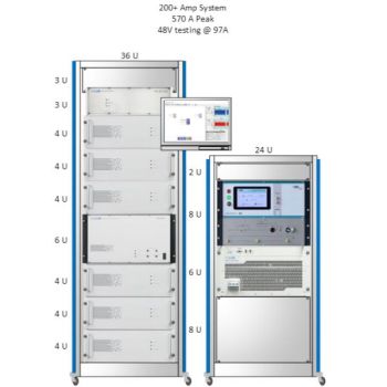
The modular system concept allows the realization of different test requirements:
· Different power supply voltages of 12V, 24V, 42V, 48V and 70V (or specific)
· Different power supply currents, nominal power supply current of 50 A, 100 A, ad 200A
Configurations for the fulfillment of various standards:
| Setup | CAR-SYS +Battery | CAR-SYS +PS xx-xx | CAR-SYS + CAR-AWG | |
| CAR-AWG | ||||
| ISO 7637 2) | Yes5) | Yes | Yes | No |
| ISO 16750 1) | No | Yes4) | Yes | Yes |
| ISO 21848 | No | Yes | Yes | Yes |
| LV 124/148 3) | No | No | Yes | Yes |
| MBN 1028-4 | Yes | Yes | Yes | No |
| Renault 36.00.808 1)Nissan 280401ND02 | No | No | Yes | No |
| SAEJ 1113-111 1) | No | No | Yes | No |
| VW TL81000 1) | Yes | Yes | Yes | No |
| …and many other standards | ||||
| 1) + Load dump (PG2804 / PS-LD) | 4) without Superimposed alternating voltage test |
| 2) + CAR-TE 14 for 4.3. Transient Emission test | 5) without Pulse 2b |
| 3) + CAR-PFS 80 for LV E-10, E-13 and E-14 Interruptions tests | |
|
Options |
Description |
| PC Software CAR-Remote(required to control power amplifiers: CAR-AWG, PS xx-xx) | control of CAR-SYS control of PG2804control of CAR-Transient Emission 14 control of CAR-PFS 80 |
| Build in 19“ Rack (9HE, 600 deep) | |
|
Expandable equipment |
Description |
|
|
|
|
CAR-AWG X |
Remote-controlled amplifier, arbitrary generator |
|
PS XX-XX |
Remote-controlled amplifier |
|
CAR-Transient Emission 14 |
Used to check the transient transition behavior, when switching (slow and fast) loads on the vehicle electrical system. |
|
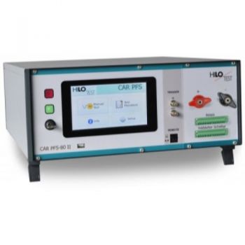
CAR-PFS 80 |
Automotive power fail simulator, which is designed for performing fast voltage dips and drops (micro- interruptions). The electronic switches in the generators allow switching times below 1 microsecond. |
|
Load Dump PG 2804 acc. to ISO 16750 |
Test A, Test B (former Pulse #5) 800J |
|
Electronic LD-PS acc. to ISO 16750 |
Electronic LD, Test A + Test B (former Pulse #5) |
|
CDN 2012 acc. to ISO 7637-3 |
Capacitive Coupling clamp |
|
ICC-F65 acc. to ISO 7637-3 |
Inductive coupling clamp |
|
CAR-CAL-KIT |
Resistor box containing all load resistors required to verify CAR pulse. |
|
BCK 400 F 2 |
Calibration Kit, to measure the pulse output voltage of burst generators |
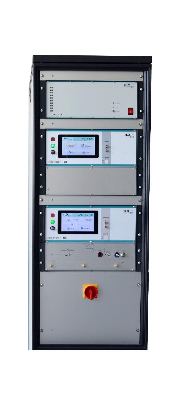
Example configuration of HILO-TEST system
CAR-TEST-SYSTEM 14 I
Pulse #1, #2 und #3, Built-in 19” Rack
-
+ Option Power Supply CAR-AWG 1200/3000/6000 Pulse #2b, #4, and more, 50A continuous current (battery load), see technical specification
-
+ Option PG 2804 Load Dump
-
+ Option CAR-PFS 80 Micro-interruptions
-
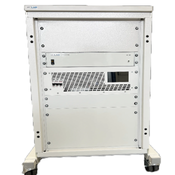
+ Option 19” rack 9HE, 600 mm deep
|
Technical specifications: |
CAR-TEST-SYSTEM 14 |
|
|
|
|
Mainframe |
|
|
Microprocessor controlled touch panel |
7”, capacitive |
|
Ethernet Interface for remote control of the generator |
built-in |
|
Interface for saving reports |
USB |
|
External trigger input /output |
Switch/ 10 V |
|
Connector for external safety interlock loop |
24 V= |
|
External red and green warning lamps acc. to VDE 0104 |
24 V=, 40 mA |
|
Cooling |
Controlled fans and heat sink |
|
Mains power |
90V - 264V, 50/60 Hz |
|
Dimensions, case, 7 HE, W * H * D |
450*310*500 mm3 |
|
Weight |
35kg |
|
Measurement Equipment Impulse voltage divider, 4.95 kW / 50 W |
100:1, 1 kV-peak |
|
|
|
|
Power supply switch: |
|
|
Output current, depending on system type |
50 A, 100 A, 200 A |
|
Max. reverse voltage |
800 V |
|
Transient over-voltage protection |
>1000V |
|
High short circuit current capability |
900A |
|
Protection with automatic circuit breaker |
50 A, 100 A, 200 A |
|
Amplifier sense line decoupled from output |
built-in |
|
Trigger input, connectable to external modules |
built-in |
|
|
|
|
Integrated Pulse forms, according ISO 7637-2, 2011 |
|
|
|
|
|
Surge Mainframe (Pulse 1 and Pulse 2a) |
(see ISO 7637-2 5.6.1/2) |
|
Charging voltage, adjustable |
± (0 - 600) V ± 10% |
|
Max. stored energy |
18 J |
|
Polarity, switchable |
positive, negative |
|
Source resistance; switchable |
150/90/50/30/20/10/4/2W |
|
Only with negative pulse polarity |
|
|
Power supply disconnection time, t2 |
(0.2-200) ms ± 20% |
|
Trigger delay, t3 |
< 100 µs |
|
Rise time, variable |
1µs - 5µs, 1µs steps |
|
|
|
|
Pulse 1 |
(see ISO 7637-2 5.6.1) |
|
Waveform |
1-5/2000µs, 1-5/1000µs or 1-5/500µs |
|
Rise time, tr |
1µs - 5µs, 1µs steps |
|
Rise time, tolerance |
1.0µs + 0/-0.5µs; 3.0µs +0/-1.5µs |
|
Pulse duration, td |
2000 µs / 1000 µs / 500µs ± 20% |
|
Rep. time, t1 |
0.5 sec – 100 sec |
|
|
|
|
Pulse 2a |
(see ISO 7637-2 5.6.2) |
|
Waveform 1/50ms |
1/50µs |
|
Rise time, tr |
1.0 µs +0µs/-0.5µs |
|
Pulse duration, td |
50 µs ± 20% |
|
Rep. time, t1 |
0.2 sec – 100 sec |
|
Technical specifications: |
CAR-TEST-SYSTEM 14 |
|
|
|
|
BURST Pulse 3a/3b ISO 7637-2, 2011 |
(see ISO 7637-2 5.6.3) |
|
Amplitude of burst output voltage, adjustable |
± (25-800) V ± 10% |
|
Waveform |
|
|
Rise time, tr |
5.0 ns ± 30 % |
|
Pulse duration, td |
150 ns ± 30 % |
|
Source resistance, Rs |
50 W |
|
Polarity, switchable |
pos / neg |
|
Pulse period t1, adjustable |
0,01 ms - 1.0 ms |
|
Burst duration t4, adjustable |
0,01 ms - 25 ms |
|
Burst period t5, adjustable |
10 ms - 1000 ms |
|
Max. continuous burst frequency |
20 kHz |


