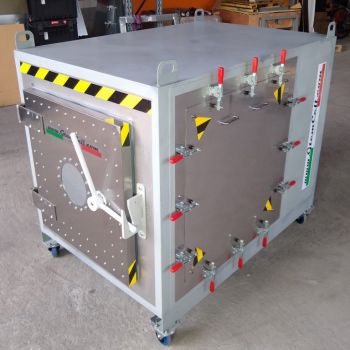
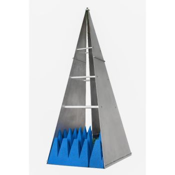
TEMZ 5233, DC - 600 MHz, Closed, unsymmetrical 50 Ohm strip line
- Closed, unsymmetrical 50 Ohm stripline
- DC - 420 (600) MHz
- Crawford TEM Cell for E- field probe and H-field probe calibration
- and for immunity testing
- ISO 11452-3, IEEE 1309 und EN 61000-4-20
PARTNER:
MARKETS:
CATEGORIES:
TEST STANDARDS:

Data Sheet
SPECIFICATIONS
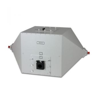
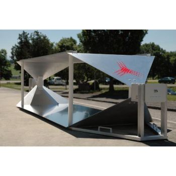
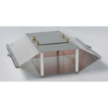
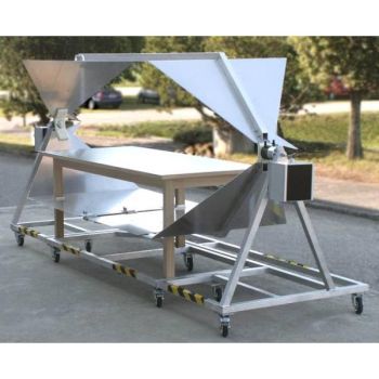
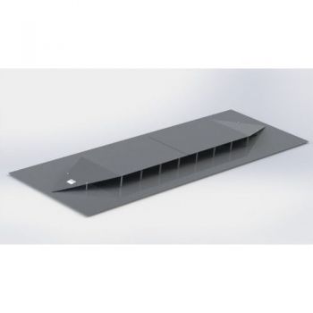
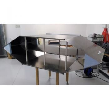
TEMZ 5233, DC - 600 MHz, Closed, unsymmetrical 50 Ohm striplineClosed, unsymmetrical 50 W stripline (also called Crawford-TEM-Cell or Transverse ElectroMagnetic cell) for E- and H-field probe calibration and immunity testing of components. The TEMZ 5233 complies to the requirements of ISO 11452-3, IEEE 1309 and EN 61000-4-20. Application: The unsymmetrical 50 W stripline complies with the requirements of ISO 11452-5. The stripline can be used to create TEM-waves up to max. 420 MHz. Thanks to the very precise design of the TEMZ 5233 very good impedance matching and extremely low transmission loss have been achieved. Therefore the cell is qualified for the Calibration of E- and H-field probes. Quick-mount probe fixtures provided to accept the field probe under test. The lower half of the cell is used for the calibration of E-field probes, the upper half is closed with the cover. The calibration of loop antennas (H-field probes) is performed in the upper half of the cell with the lower half closed by the cover. The probe orientation is depicted in the following figure. It is important to note that one port is connected to a generator and the other port to a 50 Ohm termination. Of course, the termination can also be replaced by a combination of a suitable power attenuator and 50 Ohm measuring equipment. The field strength distribution at TEM-mode operation inside the stripline is very homogenous. The ratio between E-field and H-field inside the cell is described by the characteristic impedance of free space (377 V, 51.5 dB). The stripline can also be used above 420 MHz, in this case, higher modes do exist, which exhibit location-dependent field strength characteristics and often different polarization direction as the TEM-mode.
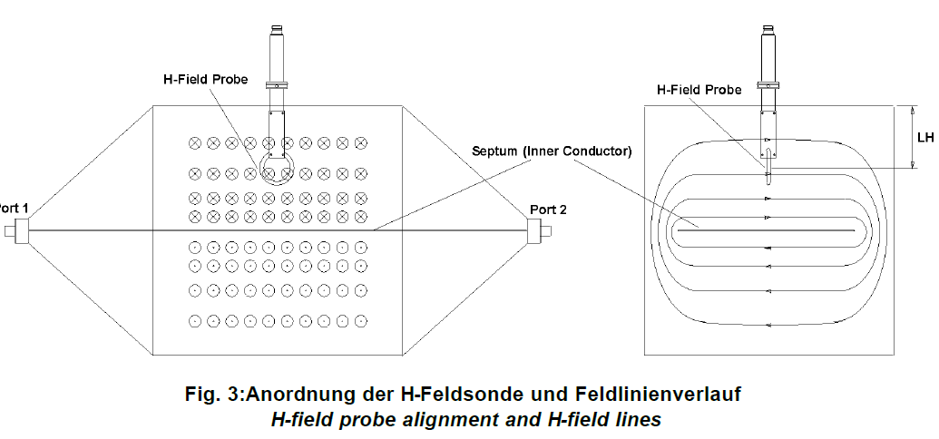
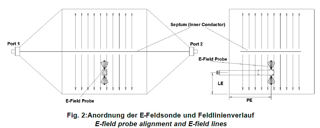
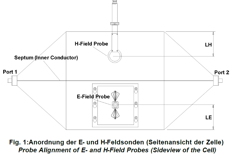
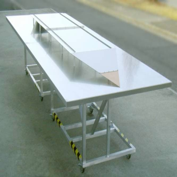
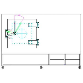
Field Characteristics and Probe Alignment: The following figures show the alignment of the field probes and simplified field characteristics in TEM-mode. The E-field lines are standing perpendicular on conductive surfaces from the septum to the walls of the cell. The H-fieldlines are closed and wrap around the inner conductor. Further, the E- and H-field lines are perpendicular to each other. When positioning an E-field probe it is important to align the probe elements parallel to the E-field lines. The positioning height LE is given at half of the septum height by the probe fixture. When positioning an H-field probe it is important that the magnetic field lines go through the loop plane. The positioning height LH is also half of the septum height and should be adjusted very carefully because this dimension has a strong effect on the calibration result. The positioning of the E-field probe PE is not very critical. The measurements of field uniformity was made using field probes with 50 mm loop diameter or 50 mm total element length respectively (HFS 1546 and EFS 9218 with shortened elements).
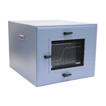
EuT Influence on Field Characteristics The influence of the EuT dimensions is negligible if the EuT is smaller than 1/3 of the septum height. The Cell is still usable for larger EuTs, if some additional points are considered. Depending on the Cell's Transmission and Reflection coefficient there are some estimations possible, how the EuT disturbs the field characteristics. For a demonstration of these effects, the transmission of the empty cell was measured first, second, an H-field probe with 50 mm diameter was inserted in the cell, and third a 120 mm E-field probe. The three transmission curves were plotted together in a diagram. The same was done for the reflection and displayed as a voltage standing wave ratio (VSWR). |
OTHER PRODUCTS IN THE SAME CATEGORY:
Open TEM Cells
PPL200 Parallel Plate Line
PPL200-70-S Parallel Plate Line
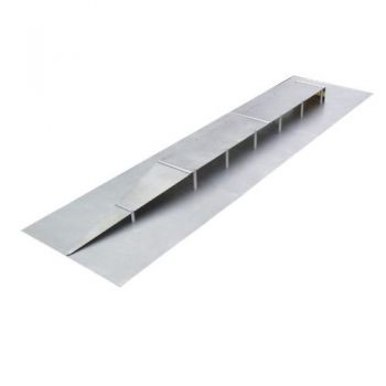
SR50 - SR90 ISO 11452-5 Striplines
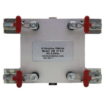
TEM-6000 STRIPLINE, 6 GHz IC Testing
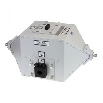
TEMZ 5234, DC - 1200 MHz, Closed, unsymmetrical 50 Ohm strip line
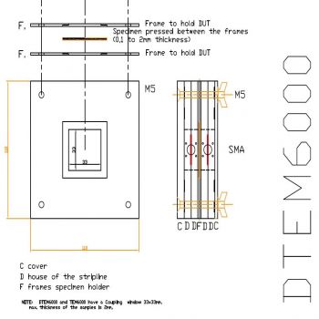
DTEM 6000 Double TEM for Shielding effectiveness
TEMZ 5232, DC - 1000 MHz, ISO 11452-5, 90 Ohm stripline
TEMZ 5231, DC - 1000 MHz, ISO 11452-5, 50 Ohm stripline
TEMZ 5233, DC - 600 MHz, Closed, unsymmetrical 50 Ohm strip line
TPD50-100-2 & TPD50-100-4, 2 & 4 Line, 100 A, LISN with TPD
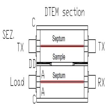
DTEM 4000 Double TEM for Shielding effectiveness
TEM Cell (Closed Cell)
Shielded Chamber and Box Solutions
EMC SHAC-200, ~700MHz-40GHz, Shielded Box Solutions
SB3G Shielded Box – EMI & RF Protection
TBTC0/1/2/3 - Open TEM Cell for EMC Pre-Compliance Testing
TBGTC1 Open GTEM Cell for EMC Pre-Compliance Testing
Discontinued Open TEM Cells

