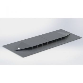
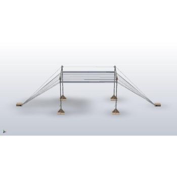
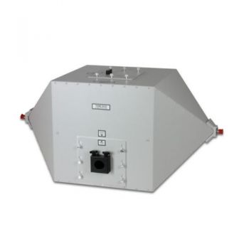
TEMZ 5231, DC - 1000 MHz, ISO 11452-5, 50 Ohm stripline
- Open, unsymmetrical 50 Ohm stripline
- DC - 220 (1000) MHz
- For immunity testing
- ISO 11452-5
PARTNER:
MARKETS:
CATEGORIES:
TEST STANDARDS:

Data Sheet
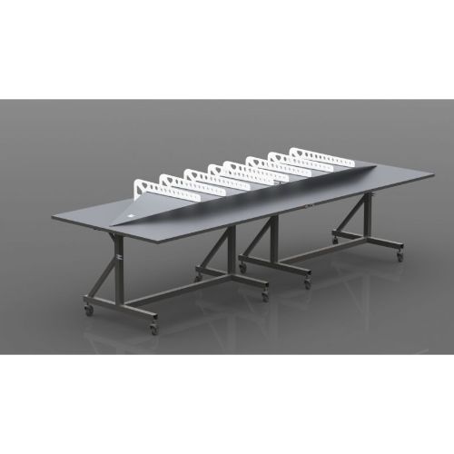
Option Foldaway
SPECIFICATIONS
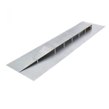
TEMZ 5231, DC - 200(1000) MHz, Open, unsymmetrical 50 Ohm striplineOpen, unsymmetrical 50 Ω stripline for automotive immunity testing of components. (A wooden frame construction is required to bear the stripline, not included in delivery) Application: The unsymmetrical 50 Ω stripline complies with the requirements of ISO 11452-5. The stripline can be used to create TEM-waves up to max. 220 MHz. The field strength distribution at TEM-mode operation inside the stripline is very homogenous. The stripline can also be used above 220 MHz, in this case, higher modes do exist, which offer a location dependant field strength characteristics. In contrast to the TEM-mode, where the field strength is small at the edge of the stripline and increases towards the center, the higher modes show opposite characteristics: the field strength is small at the center of the stripline and rises to maximum values at the edge of the strip conductor. Further, the direction of polarisation changes in some areas during multi-mode operation. At TEMmode operation there are only small losses caused by radiation and dielectric losses of the plastic support rods. Less than 1% of the incident power is reflected back into the source, caused by minimized impedance mismatch. The dielectric and radiation losses at TEM operation frequencies are as follows: |S21| = 0.5 dB, losses: 11%, |S21| = 1.0 dB, losses: 21%,|S21| = 1.5 dB, losses: 29%. The losses increase for multi-mode operation, at 380 MHz only 50% of the feed power is available at the output connector. At 800 MHz only 25%, at 1 GHz only 12% of the feed power is available at the output connector. An ideal tool for monitoring the actual field strength inside the stripline is the VUFM 1670 field meter with VUFM 1671 LCD display unit, which are connected via a fiber optical link. For positioning of the EuT it is recommended to use (nearly) dielectric neutral material, e.g. foam or polystyrene plastics. The suitability of the material can be checked as follows: the insertion loss of the empty cell is measured, then the material under test is placed in the cell and the insertion loss is measured again. Minimum differences in attenuation of the empty and loaded cell indicate a suitable material. The equipment under test (EuT) should be placed in the center of the stripline. It is recommended to record the EuT-position as exactly as possible in order to achieve a good reproducibility of the tests.
Options: Opt. Termination 150 W: 50 Ohm termination, N-jack,150 Watt, connecting cable for TEMZ 5231
Opt. Termination 500 W: 50 Ohm termination, N-jack, 500 Watt, connecting cable for TEMZ 5231
Opt. Foldaway: Instead of cylindrical rods to hold the septum, there will be sidearms. The cell can be folded away vertically. Stainless steel construction with caster wheels supports the cell. Must be ordered together with TEMZ 5231, cannot be refitted.
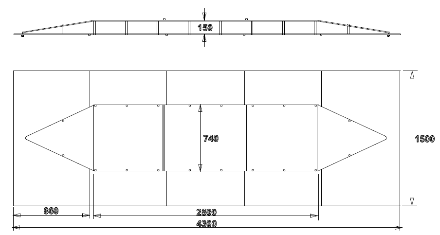
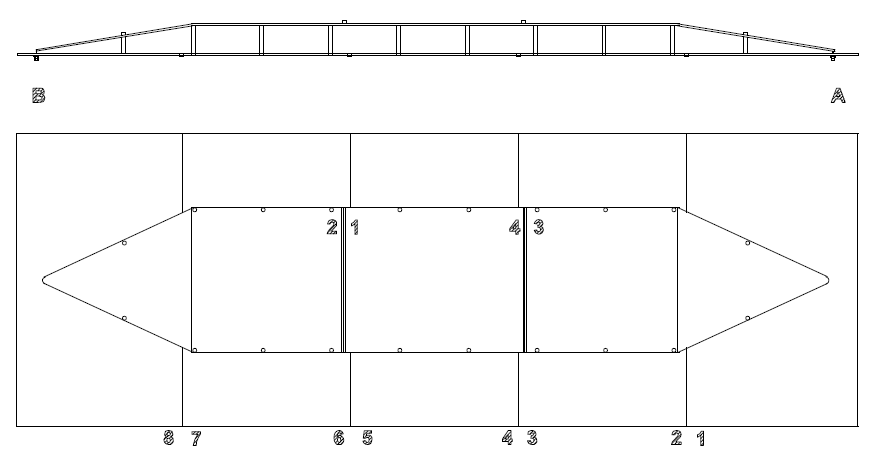
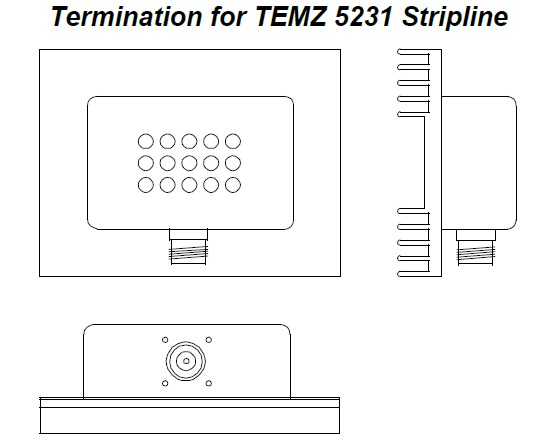
Mounting the TEMZ 5231 Stripline The TEMZ 5231 requires a plain and rugged construction for mounting and operation, e.g. a wooden frame. The stripline can not be used without such a construction! We recommend contacting a local joiner to build a suitable bearing frame. In order to save space, the stripline can also be mounted in a vertical position, e.g. at the wall of a shielded room. The mounting of TEMZ 5231 is made by two persons, the required tool is a cross-screwdriver (PHILLIPPS RECESS Size 1). At first, all delivered parts should be identified and checked for completeness. The drawing below shows a side and top view with some numbers. In order to provide an accurate fitting of the parts, the mounting numbers should be considered according to the drawing. The mounting numbers 2, 1, 4, 3 of the 74 cm wide upper conductor are visible from above, the mounting numbers of the large ground conductor, consisting of 5 aluminum plates 0.86 x 1.5 m and 4 connecting parts (8,7,6,5,4,3,2,1) are visible on its bottom side. First, the 5 large aluminum plates are mounted together using the 4 connecting parts and screws, both N-connectors and connecting parts are oriented downwards. In the next step, the 16 white plastic rods (20 x 150 mm) are mounted on the ground conductor. Further 4 plastic rods with sloped top-ends are needed for the two tapered sections. These sloped rods are mounted on the ground conductor preliminary, the fine adjustment and fixation is made later. The upper conductor plate (92.5 x 74 cm) and the two tapered plates are placed onto the plastic rods and mounted together using two connecting parts (oriented to the top). The complete upper conductor can now be moved slightly in order fit to the corresponding threads of the plastic rods and to both N-connectors. It is important to avoid mechanical stress to the inner conductors of the N-connectors! The sloped rods at the tapered sections can be adjusted now and all screws can be tightened with a reasonable torque. Finally, the N-connectors are fixed to the tapered sections. Termination for TEMZ 5231 Stripline Termination resistor mounted on a finned aluminum heatsink with female N-connector. The termination is for connection to the open, unsymmetrical 50 W stripline TEMZ 5231. Safety Precautions: The termination resistor may reach high temperatures. Good air circulation must be provided in order to avoid excessive heating. It is recommended to place the termination resistor with vertical aligned cooling fins. For steady high power use, an additional fan is appropriate to avoid high temperatures. Keep combustible material away from the termination, be aware of a fire hazard! The termination resistor may radiate electromagnetic fields when driven with high power, therefore the safety standards for persons exposed to electromagnetic fields must be respected (e.g. VDE 0848).
|
OTHER PRODUCTS IN THE SAME CATEGORY:
Open TEM Cells
PPL200 Parallel Plate Line
PPL200-70-S Parallel Plate Line
GENE-H-30-3K E/H 10kHz to 30MHz Field Generator / Stripline
SR50 - SR90 ISO 11452-5 Striplines
TEM-6000 STRIPLINE, 6 GHz IC Testing
TEMZ 5231, DC - 1000 MHz, ISO 11452-5, 50 Ohm stripline
TEMZ 5232, DC - 1000 MHz, ISO 11452-5, 90 Ohm stripline
PPL200-70-C Parallel Plate Line
Open TEM Cells
PPL200 Parallel Plate Line
PPL200-70-S Parallel Plate Line
SR50 - SR90 ISO 11452-5 Striplines
TEM-6000 STRIPLINE, 6 GHz IC Testing
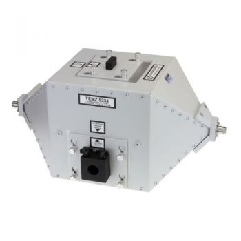
TEMZ 5234, DC - 1200 MHz, Closed, unsymmetrical 50 Ohm strip line
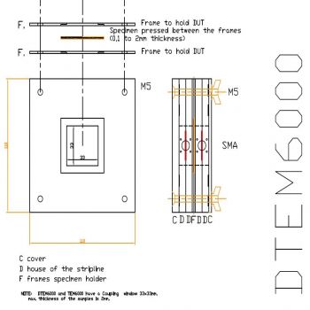
DTEM 6000 Double TEM for Shielding effectiveness
TEMZ 5232, DC - 1000 MHz, ISO 11452-5, 90 Ohm stripline
TEMZ 5231, DC - 1000 MHz, ISO 11452-5, 50 Ohm stripline
TEMZ 5233, DC - 600 MHz, Closed, unsymmetrical 50 Ohm strip line

