What is needed to measure conducted emissions for EMI?
What is needed to measure conducted emissions for EMI?
To build up a system and test setup for conducted emissions, you need to know and understand all the critical components. The test standard you follow will list and explain all the equipment needed and its required specifications.
List of Equipment Required
- EMI Receiver – Real-time CISPR 16 compliant
- Test Software – Automation and Reporting
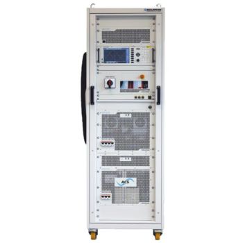
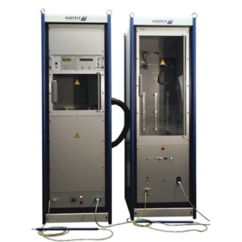
- LISN – Line Impedance Stabilization network
- Transient Limiter – protection of receiver from high voltage transient of LISN
- Coax Cables – for connections
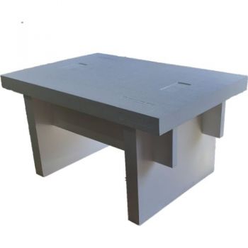
- Test Table
- Ground Plane/s
- Optional: Power Filtering and/or Shield room
Other tools are required to evaluate failures and troubleshoot possible fixes.
- Splitter and Combiner to evaluate Common Mode and Differential Mode EMI emissions.
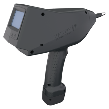
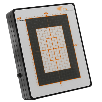
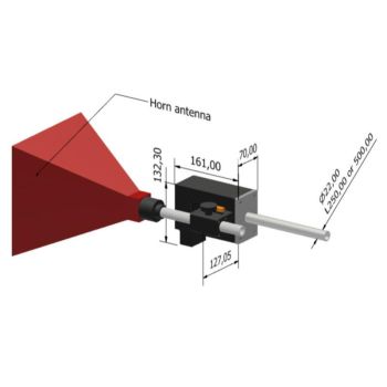
- Near Field Sniffer Probes to pinpoint locations of EMI emissions.
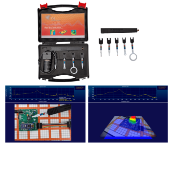
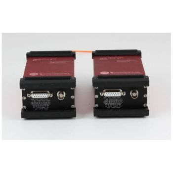
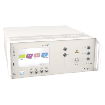
The Items boxed in purple are part of the EMSCOPE. This device allows for a very simplified test setup but increases your troubleshooting and product evaluation by adding a second real-time receiver. This allows for measuring both Line and Neutral (DC+/-) at the same time, seeing Peak, Quasi-Peak (QP), and Average (AVG). This is 6 traces all at once.
But it can also evaluate Common Mode and Differential Mode measurements of the EUT. Discover instantly how the product is falling, find a solution faster, and pass your testing. No other product on the market can do this so fast and effectively.
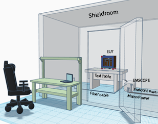
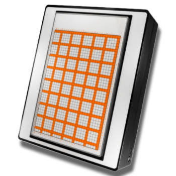
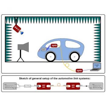
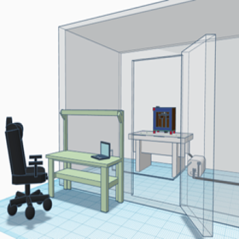
The basic setup of EUT in a shielded room (see-through walls) EUT on a non-conducted table with,
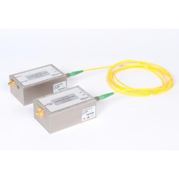
EMSCOPE (LISN/Receiver) is located on and bonded to the ground plane. PC connected with fiber optic cables.
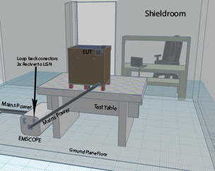
The internal LISN is capable of supporting 16A / 300V AC or DC. It is a 50uH LISN in compliance with CISPR 16. If other tests are required that require more power or different LISN types. The EMSCOPE can be connected to these external LISNs.
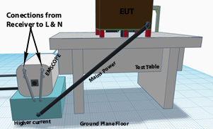
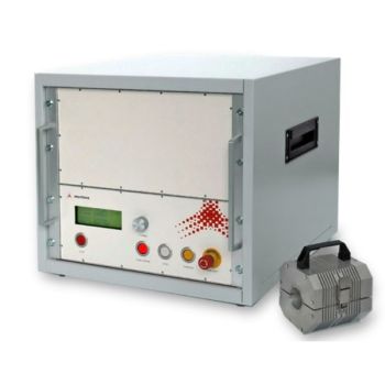
Connections to a larger current LISN
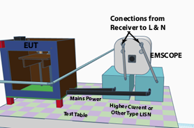
Setup for MIL or CISPR 25 on the benchtop and separate LISNs
The EMSCOPE also comes in a 4-receiver version to test 3-phase power. In this case, 4 lines (3 phase + Neutral) are connected to the 3 phase LISN. Please Note: The LISN needs to separate each line with a connector and not switched.
|
Models |
|||||||
|
|
Freq. Range |
Receiver channels |
Transient Limiters |
Internal 1P LISN |
110-MHz |
Fiber/ETH converter |
Software |
|
EMSCOPE |
9KHz – 30MHz |
2 |
2 |
Yes |
Available |
Included |
Included |
|
EMSCOPE RX2 |
9KHz – 30MHz |
2 |
2 |
No |
Available |
Included |
Included |
|
EMSCOPE RX4 |
150KHz – 30MHz* |
4 |
4 |
No |
Available |
Included |
Included |
|
EMSCOPE RX4 LZ2 |
150KHz – 30MHz* |
4 |
4 |
Yes |
Available |
Included |
Included |
*In 4-receiver mode, the low end is limited to 150kHz. When in 2-receiver mode, the low end can be extended down to 9kHz. This is switched in the software interface