VBA250 Series — 10 kHz to 250 MHz Class-A RF Power Amplifiers
- Class-A architecture
- Push-pull MOSFET output
- Wideband 10 kHz–250 MHz
- Unconditional stability & extreme VSWR tolerance
- Integrated digital interfaces (select models)
PARTNER:
MARKETS:
CATEGORIES:
TEST STANDARDS:
Select Options/Sizes:

VBA250-80 Data Sheet
VBA250-120 Data Sheet
VBA250-200 Data Sheet
VBA250-400 Data Sheet
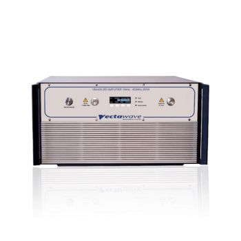
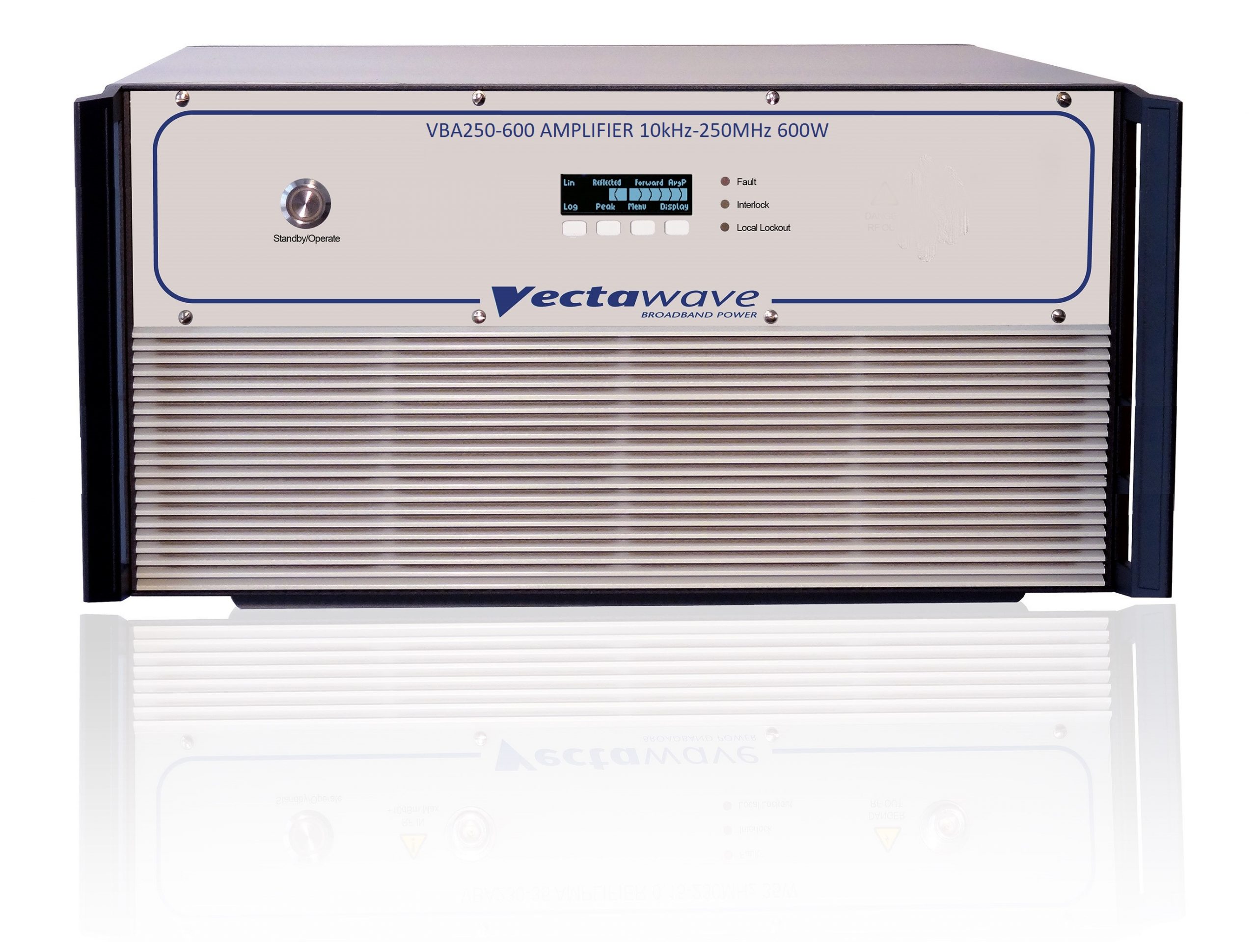
VBA250-600 Data Sheet
VBA250-800 Data Sheet
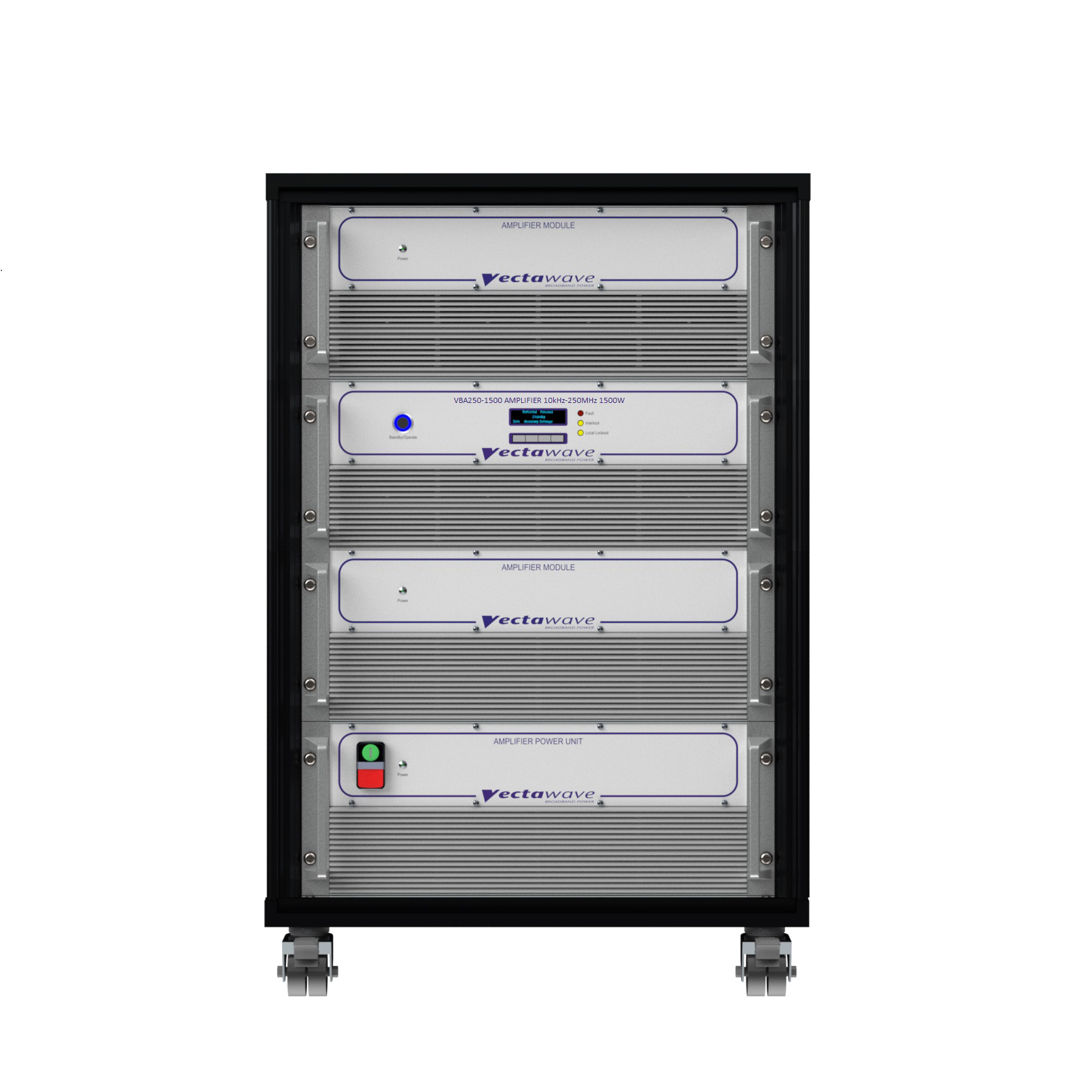
VBA250-1500 Data Sheet
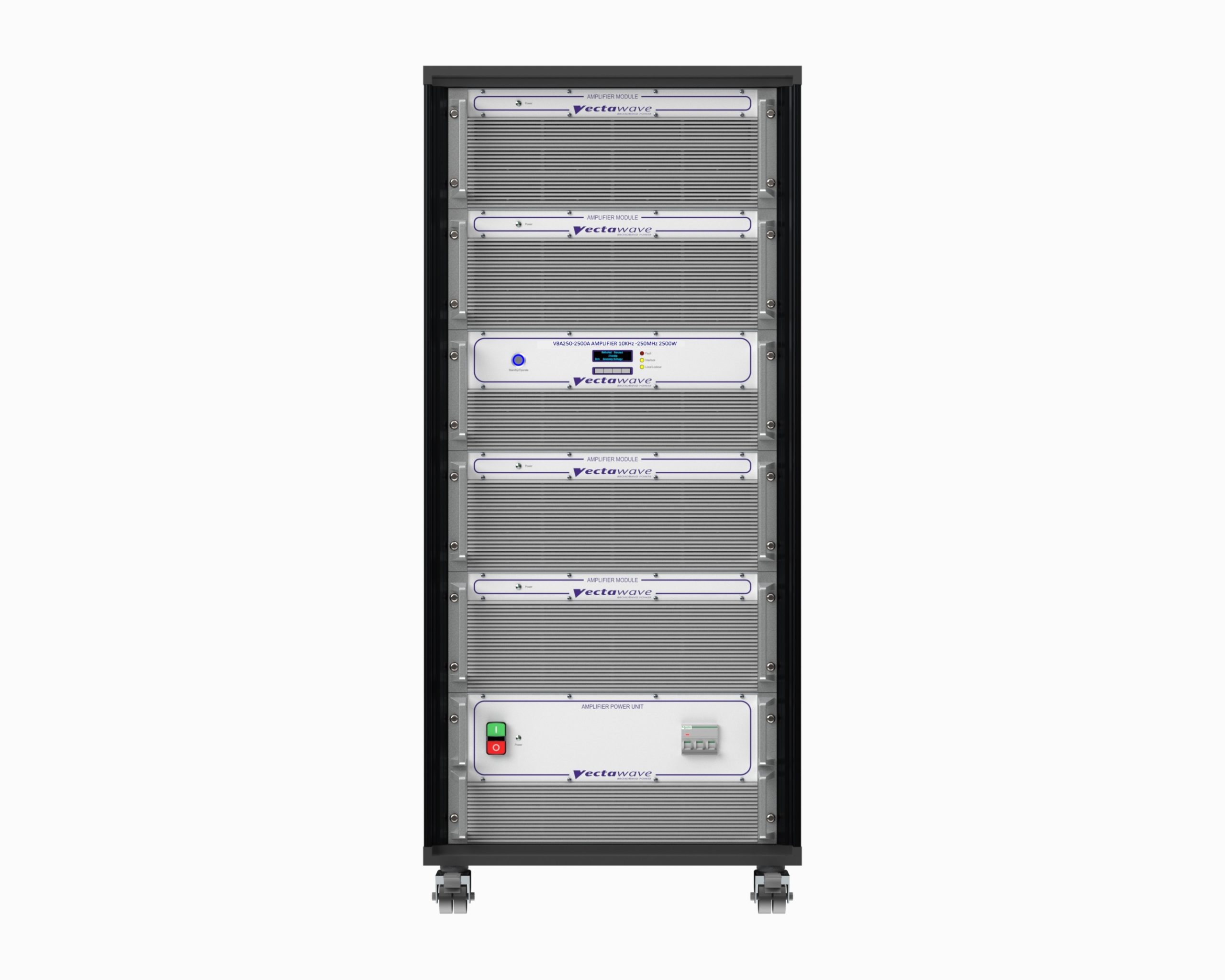
VBA250-2500 Data Sheet
SPECIFICATIONS
VBA250 Series — 10 kHz to 250 MHz Class-A RF Power Amplifiers
Broadband, mismatch-tolerant RF power for EMC immunity and transducer drive
The VBA250 Series covers 10 kHz–250 MHz with true Class-A linearity and push-pull MOSFET output stages. The result is low distortion, high reliability, and unconditional tolerance of severe load mismatch—ideal for Bulk Current Injection (BCI), IEC 61000-4-6 conducted immunity, and demanding transducer/fixture drive.
Key Technical Advantages
-
Class-A architecture for lowest distortion in immunity testing and stable operation into difficult loads; no fold-back needed during high reflection, ensuring full output even with open/short conditions.
-
Push-pull MOSFET output topology suppresses even-order harmonics for cleaner spectra during test.
-
Wideband 10 kHz–250 MHz coverage across the series for conducted RF, BCI, TEM/stripline, and small fixture/antenna drive.
-
Unconditional stability & extreme VSWR tolerance (continuing at full power into open/short); suitable for varying BCI clamp impedances.
-
Integrated digital interfaces (select models), including USB/GPIB for control/monitoring and interlocks.
Models & Core Specifications
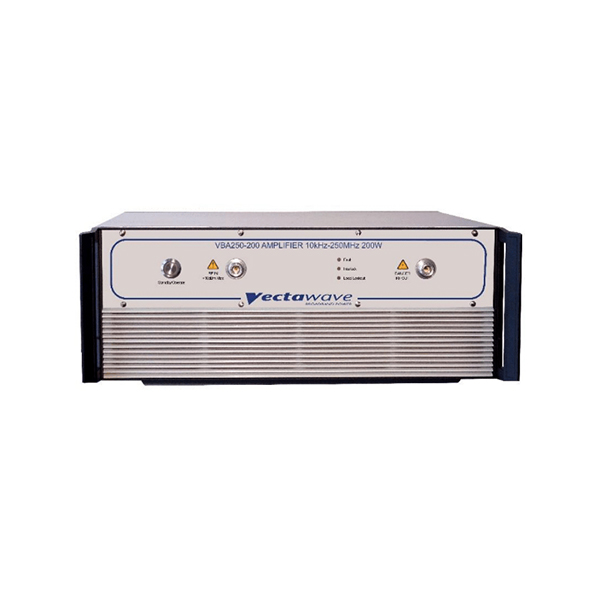
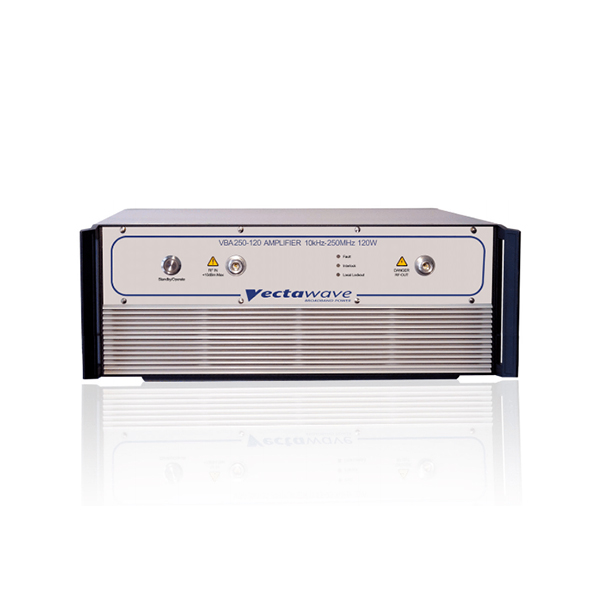
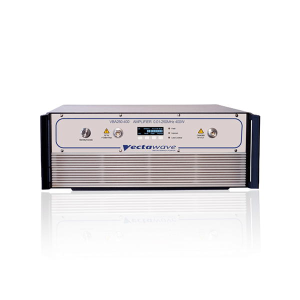
| Specification | VBA250-80 | VBA250-120 | VBA250-200 | VBA250-400 | VBA250-600 | VBA250-800 | VBA250-1500A | VBA250-2500A |
|---|---|---|---|---|---|---|---|---|
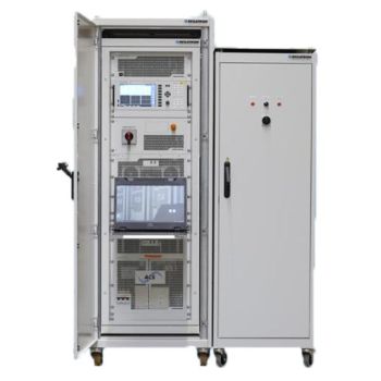
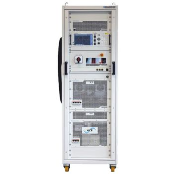
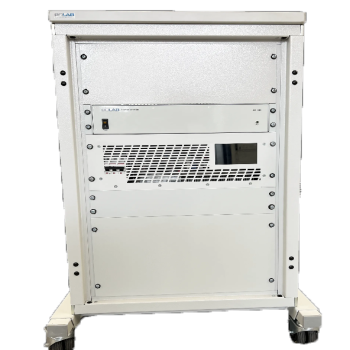
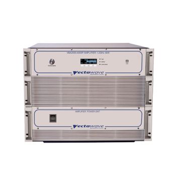
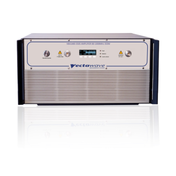
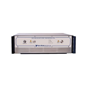
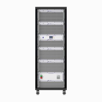
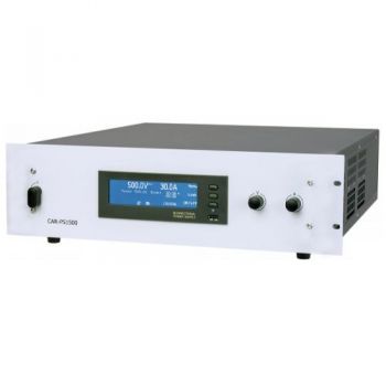
| Picture | 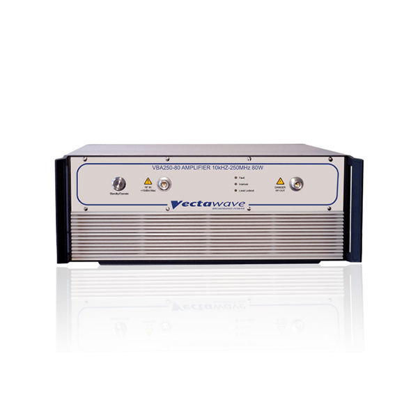 |
 |
 |
 |
 |
 |
 |
|
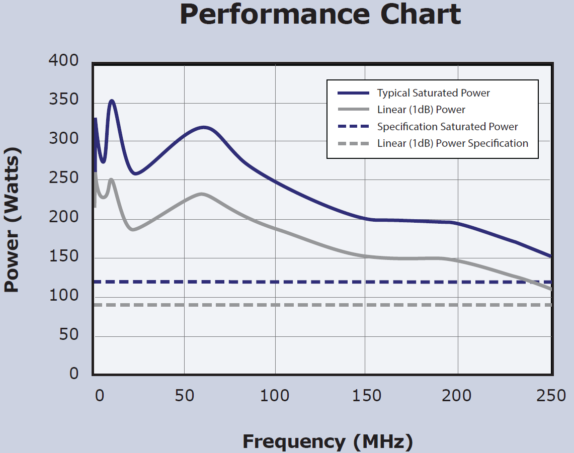
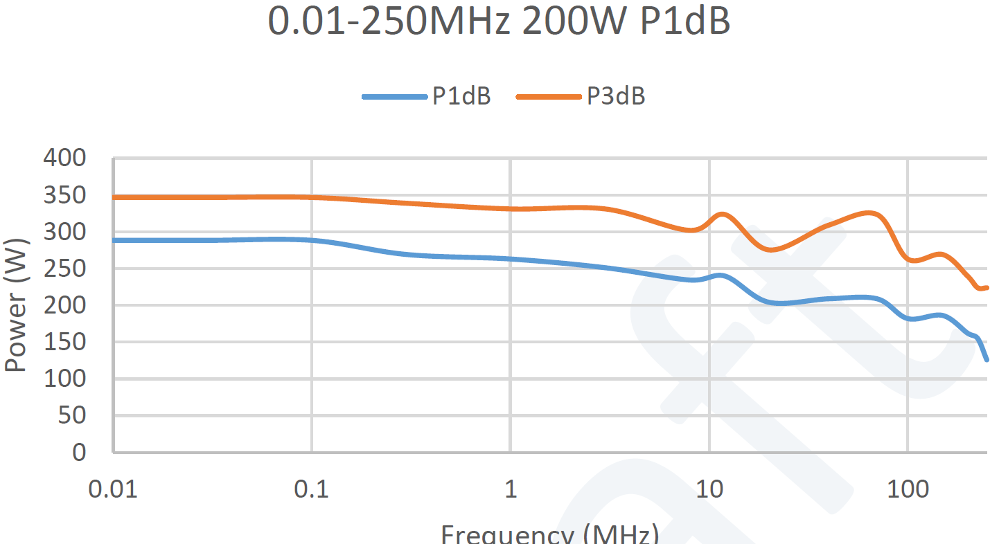
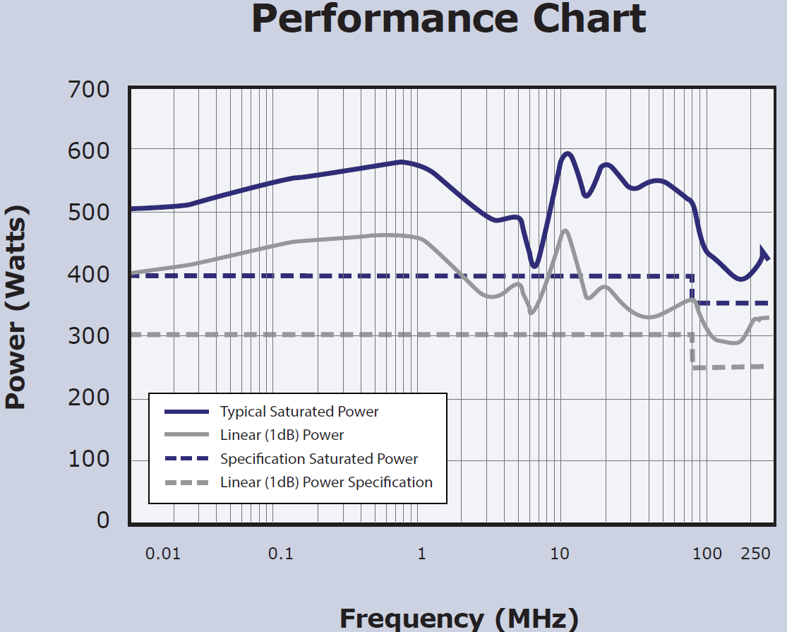
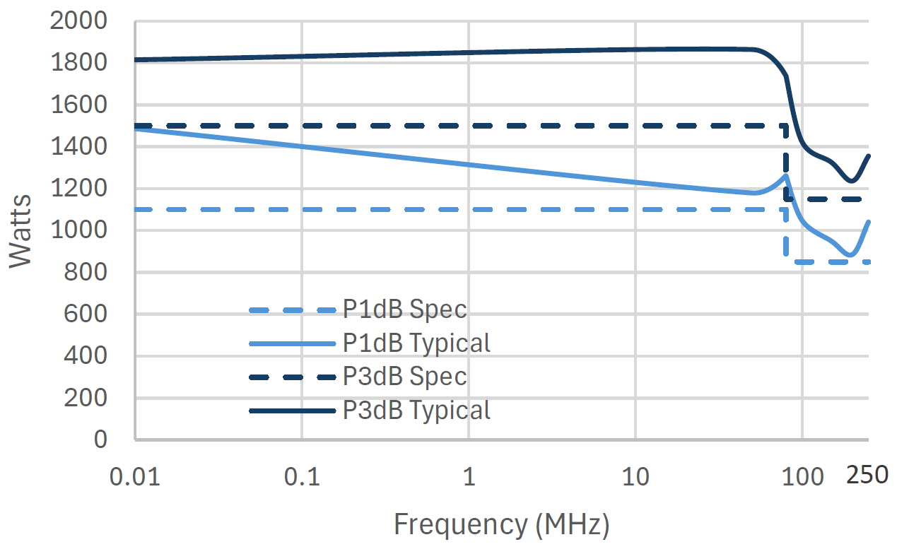
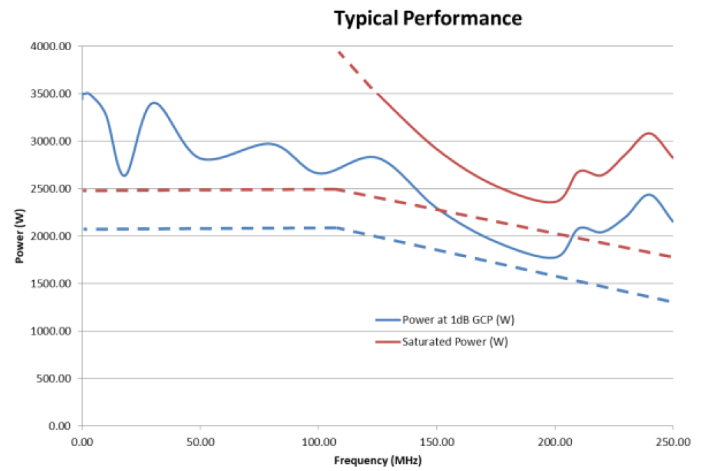
| Typ. Performance Curve | 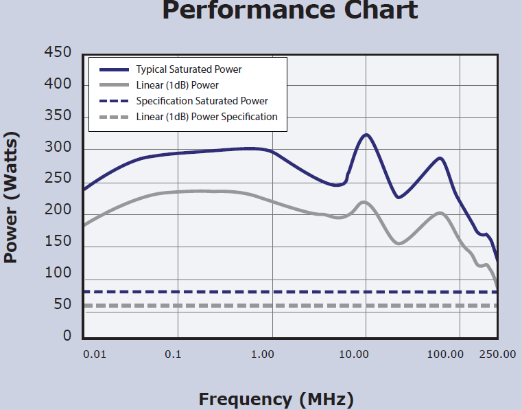 |
 |
 |
 |
 |
 |
||
| Frequency Range | 10 kHz–250 MHz | 10 kHz–250 MHz | 10 kHz–250 MHz | 10 kHz–250 MHz | 10 kHz–250 MHz | 10 kHz–250 MHz | 10 kHz–250 MHz | 10 kHz–250 MHz |
| Type | Class-A; rugged push-pull MOSFET |
Class-A; rugged push-pull MOSFET |
Class-A; rugged push-pull MOSFET |
Class-A; rugged push-pull MOSFET |
Class-A; rugged push-pull MOSFET |
Class-A; rugged push-pull MOSFET |
Class-A; rugged push-pull MOSFET |
Class-A; rugged push-pull MOSFET |
| Output VSWR Tolerance | ∞:1, 100 % mismatch tolerant |
∞:1, 100 % mismatch tolerant |
∞:1, 100 % mismatch tolerant |
∞:1, 100 % mismatch tolerant |
∞:1, 100 % mismatch tolerant |
∞:1, 100 % mismatch tolerant |
∞:1, 100 % mismatch tolerant |
∞:1, 100 % mismatch tolerant |
| Rated / Typical Power | CW ≥80W, P1dB ≥60W (>80W typ.) |
CW ≥120 W, P1dB ≥90 W (120 W typ.) |
CW ≥250W (10kHz-80MHz), ≥200W (80-250MHz), P1dB ≥200W (10kHz-80MHz),≥150W (80-225MHz) |
CW ≥400W (10kHz-80MHz), ≥360W (80-250MHz), P1dB ≥300W (10kHz-80MHz), ≥250W (80-250MHz) |
CW ≥600W (10kHz-80MHz), ≥550W (80-250MHz), P1dB ≥500W (10kHz-80MHz), ≥400W (80-250MHz) |
CW ≥800W (10kHz-80MHz), ≥650W (80-250MHz), P1dB ≥650W (10kHz-80MHz), ≥500W (80-250MHz) |
CW ≥1500W (10kHz-80MHz), ≥1150W (80-250MHz), P1dB ≥1100W (10kHz-80MHz), ≥850W (80-250MHz) |
CW ≥2500W (10kHz-100MHz), ≥1900W (100-250MHz), P1dB ≥2100W (10kHz-100MHz), ≥1300W (100-250MHz) |
| Gain (min) | 50 dB | 51 dB | 54 dB | 56 dB | 63 dB | 63 dB | 63 dB | 64 dB |
| Gain Flatness | ±2 dB | ±2 dB | ±2 dB | ±2 dB | ±2 dB | ±2 dB | ±3 dB | ±3 dB |
| TOI (typ) | 58 dBm | 61 dBm | 64 dBm | 66 dBm | 67 dBm | 67 dBm | 69 dBm | 70 dBm |
| Harmonics @ Linear Power | < –20 dBc | < –20 dBc | < –20 dBc | < –20 dBc | < –20 dBc | < –20 dBc | < –20 dBc | < –20 dBc |
| RF Input / Output Connectors | Type N (f) | Type N (f) | Type N (f) | Type N (f) | Type N (f) | Type N (f) | Input type N (f), output 7/16 (f) | Input type N (f), output 7/16 (f) |
| Input Power (Mains) | 100-240V ac 45-63Hz, <1kVA IEC320 |
100-240V ac 45-63Hz, <1kVA IEC320 |
100-240V ac 45-63Hz, <1kVA IEC320 |
100-240V ac 47-63Hz, <1.5kVA IEC320 |
184-264V ac 47-63Hz, <3kVA IEC320 |
184-264V ac |
3 phase 200-240V or 350-415V ac |
3 phase 200-240V or 350-415V ac |
| Size & Weight | 19-inch, 4U Case, 500mm Deep, 18kg | 19-inch, 4U Case, 500mm Deep, 18kg | 19-inch, 4U Case, 500mm Deep, 18kg | 19-inch, 4U Case, 650mm Deep, 33kg | 19-inch, 6U Case, 550mm Deep, 33kg | 19-inch, 6U Case, 550mm Deep, 33kg | 19-inch Rack, 16U Case, 800mm Deep, 150kg | 19-inch Rack, 25U Case, 800mm Deep, 291kg |
| Interface | non, Opt. USB/GPIB Interface | non, Opt. USB/GPIB Interface | non, Opt. USB/GPIB Interface | USB/GPIB control; front panel display. | USB/GPIB control; front panel display. | USB/GPIB control; front panel display. | USB/GPIB control; front panel display. | USB/GPIB control; front panel display. |
| Notes | Front or Rear connectors | Front or Rear connectors | Front or Rear connectors | Front or Rear connectors | Rear connectors | Rear connectors | Rear connectors | Rear connectors |
Common characteristics (series): Class-A operation, rugged push-pull MOSFET output stages, mismatch tolerance for EMC, broadband instantaneous bandwidth.
EMC Applications & Standards Coverage
-
Conducted RF Immunity (Coupling/Decoupling Networks): IEC/EN 61000-4-6.
-
Automotive BCI/RI (clamp drive and forward-power control): ISO 11452-4, SAE J1113-4.
-
Military Conducted Susceptibility: MIL-STD-461 CS114 BCI
- Avoionics Conducted Susceptibility: RTCA DO-160 Section 20 BCI testing
-
Fixture/Transducer Drive: TEM/stripline fixtures, small RF antennas, current clamps, and injection probes across 10 kHz–400 MHz.
Control, Monitoring & Protection (Model-Dependent)
-
Local front-panel metering and interlocks; USB/GPIB remote control/monitoring on higher-power units (e.g., VBA400-260).
-
Designed for continuous duty in varying matches without fold-back, maintaining linear performance for repeatable immunity levels.
Why Absolute EMC
Absolute EMC provides application-specific system design (BCI loops, clamps, CDN selection, power meters/couplers, LISNs), installation, and correlation guidance to IEC, ISO, SAE, DO-160, and MIL standards—so your amplifier integrates correctly with sensors, control, and calibration chains from day one.
What to Specify (Selection Guide)
-
Required test method & level (e.g., IEC 61000-4-6 level X, ISO 11452-4 forward power for clamp Y).
-
Fixture/transducer type and insertion loss.
-
Required linear output (P1dB) at the highest frequency of interest.
-
Available mains power and control interface needs (USB/GPIB).
-
Space/rack constraints and RF connectorization.
Typical System Block
Signal source / RF generator → leveling & power meter/coupler → VBA 250 amplifier → CDN / BCI clamp/transducer → EUT, with reverse-power/VSWR monitoring and interlocks routed to the amplifier (∞:1 VSWR tolerance and unconditional stability on models like VBA400-260 simplify integration).
Frequently Asked Questions
Q1. Will the amplifier survive a severe mismatch from my clamp or CDN?
Yes. The series is designed for EMC use with 100% mismatch tolerance, and models like the VBA250-2500 explicitly state that they operate at full power even with open/short circuits.
Q2. Do I size by rated (P3dB) or linear (P1dB) power?
For immunity targets, size to P1dB at the top frequency to preserve linearity margin; see model-specific P1dB
Q3. Can I remote-control the amplifier?
Yes—higher-power models provide USB/GPIB for enabling, metering, health, and interlock management.
Ordering Information
-
Models: VBA250-80, -120, -200, -400, -600, -800, -1500, -2500 (10 kHz–250 MHz series; note model-specific start frequencies per datasheet).
-
Included: Amplifier, mains cable, user manual; interface kit where applicable.
-
Options/Accessories: RF directional couplers & power meters, BCI clamps, CDNs, TEM/stripline fixtures, control/monitoring packages.
-
Warranty & Support: Provided by Absolute EMC with commissioning assistance and application support.
OTHER PRODUCTS IN THE SAME CATEGORY:
Dips-Interrupts-Variations Test System 30kVA (43A) & 50kVA (75A) + 1 & 3-Phase
305-AC, 0-305V, 30->1050kVA, AC Power Supply
3000-1C, 0-3000V, 54-2000+kW, DC Power Supply, Sink/Source
2000-1C, 0-2000V, 36-2000+kW, DC Power Supply, Sink/Source
VBA2000P Series — 1 to 2 GHz Class-AB Pulse RF Power Amplifiers
1500-1C, 0-1500V, 27-2000+kW, DC Power Supply, Sink/Source
1000-1C, 0-1000V, 18-2000+kW, DC Power Supply, Sink/Source
500-1C, 0-500V, 9-2000+kW, DC Power Supply, Sink/Source
320-1C, 0-320V, 36-2000+kW, DC Power Supply, Sink/Source
240-1C, 0-240V, 27-2000+kW, DC Power Supply, Sink/Source
160-1C, 0-160V, 18-2000+kW, DC Power Supply, Sink/Source
60-1C, 0-60V, 9-2000+kW, DC Power Supply, Sink/Source
80-1C, 0-80V, 9-2000+kW, DC Power Supply, Sink/Source
VBA400 Series — 10 kHz to 400 MHz Class-A RF Power Amplifiers
VBA1000 Series — 80 to 1000 MHz Class-A RF Power Amplifiers
VBA1060 Series — 1 to 6 GHz Class-A RF Power Amplifiers
VBA250 Series — 10 kHz to 250 MHz Class-A RF Power Amplifiers
VBA100 Series — 10 kHz to 100 MHz Class-A RF Power Amplifiers
CAR PS 1500, 1500V Battery Simulator

