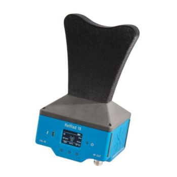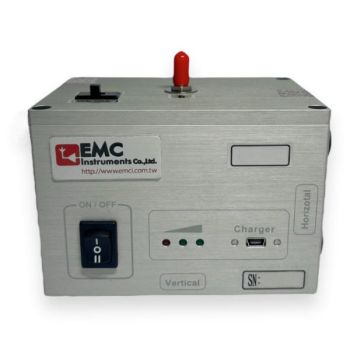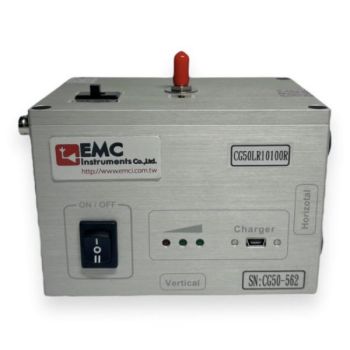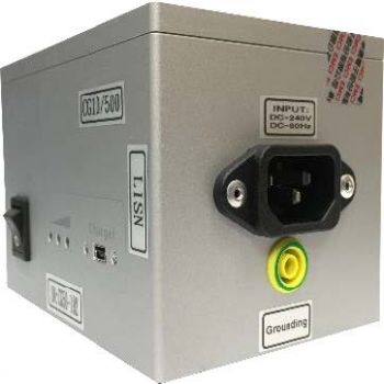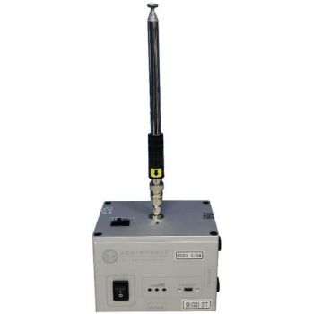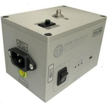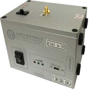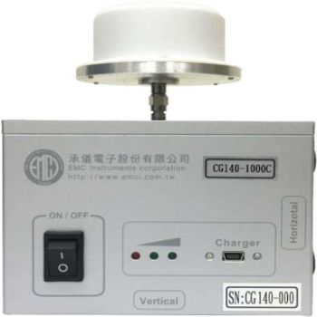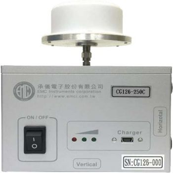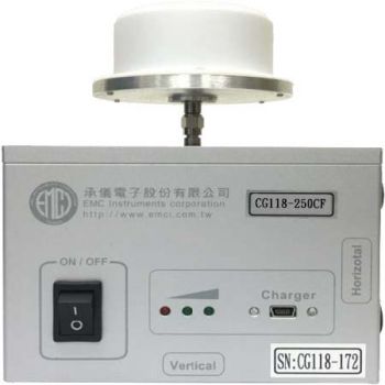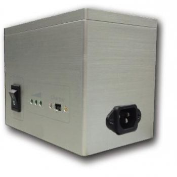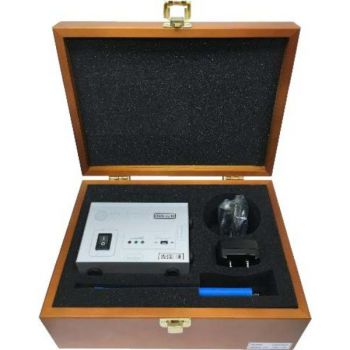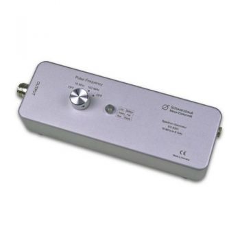
SG 9303, 0.01 - 8 GHz Comb Generator
- Spectrum Generator
- 10 MHz - 8 GHz
- spectrum lines 10 & 100 MHz
- N-female connector
- charger ACS 110 required
- main application: reference radiator requires an antenna
SG 9303, 0.01 - 8 GHz Comb GeneratorThe comb generator SG 9303 is battery powered. It provides a frequency comb up to more than 8 GHz. The spacing between the spectral lines can be switched between 10 MHz and 100 MHz. A quartz crystal provides accurate frequencies. Due to its handy size and little weight as well as the mains independent power supply, the SG 9303 is a great reference radiation source. In conjunction with a transmit antenna the comb generator plays the role of an artificial reliable EuT, while the rest of the field-strength measurement setup, consisting of receive antenna, cable, preamplifier, and receiver or spectrum analyzer can be verified.
The SG 9303 is also suitable to check the functionality of EMI test receiver or spectrum analyzers. Cables and attenuators can also be tested.
A dual-color LED indicates the charge state of the battery.
Practical measurement Amplitudenspektrum Spectrum (Amplitude) The spectrum provided by the SG 9303 ranges from 10 MHz respectively 100 MHz up to more than 6 GHz. Within the range below 1 GHz, single spectral lines might show significantly lower levels. Thus the nominal frequency range starts at 1 GHz. The amplitude of the spectrum shows a continuous decay towards higher frequencies with some minor "ripple". The SG 9303 needs 3 minutes to warm up after powering up or after changing the pulse frequency until it delivers a stable output signal. Stability of frequency To generate the base frequency standard quartz crystal generators are being used. They do not provide the possibility to correct the output frequency. Since the spectral frequencies are harmonics of the corresponding quartz frequency their deviation multiplies. Thereby the difference of the frequency can be several kHz. Above 1 GHz (band E) it is common to work with a bandwidth of measurement of 1 MHz. Thus possible deviations do not really become noticeable. For more accurate measurements the frequency tuning should be done manually to the maximum of the amplitude. Typical measurements The SG 9303 has been connected directly to the spectrum analyzer using an N-male / N-male adapter and a 10 dB attenuator for this measurement. The voltage levels of the spectral lines are listed in the table on page 7 in dBμV. To obtain the power levels in dBm, 107 dB has to be subtracted from the voltage level in dBμV. |


