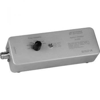
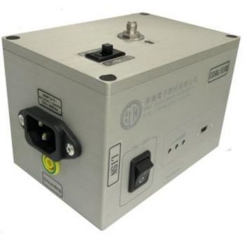
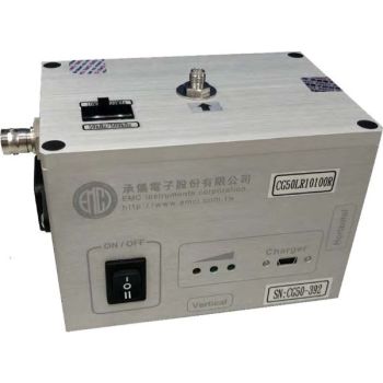
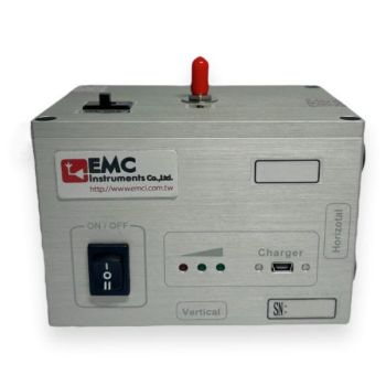
SG 9301, 1-1000MHz Comb Generator
- Spectrum Generator
- 30-1000 MHz
- spectrum lines switchable 100 Hz, 1 kHz, 10 kHz, 100 kHz, and 1 MHz
- N-female connector
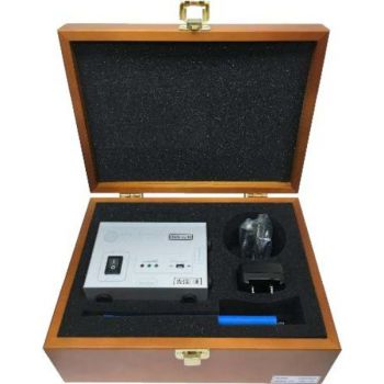
- charger ACS 110 required
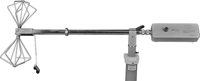
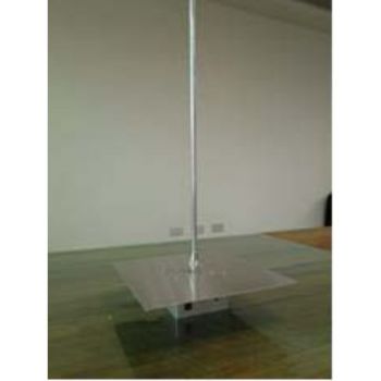
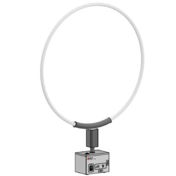
- main application: reference radiator (antenna required e.g. UBAA 9114 with BBVU 9135)

Data Sheet
SPECIFICATIONS
SG 9301, 1-1000MHz Comb GeneratorCheck out our Comb Generator Selection Guide.
The Spectrum Generator SG 9301 is a family member of the Schwarzbeck pulse generators, which are used as pulse standard worldwide. Obviously, there are some parallels to the IGUF 2910 S. Whilst the latter one uses a bounce free relay contact to discharge a coaxial line to the load resistor, the SG 9301 uses a special avalanche transistor instead of the relay contact. The transistor cannot switch the very high voltages as the relay can, but on the other hand advantages like small outlines, position-independent operation and the choice of five pulse frequencies make it very useful.
In contrast to usual generators for calibration field sources which produce a high number of harmonics by extreme driving of non-linear semiconductors at relatively low power supply voltage, the avalanche generator uses a coaxial line and a high, constant DC-voltage to determine pulse duration and pulse amplitude.
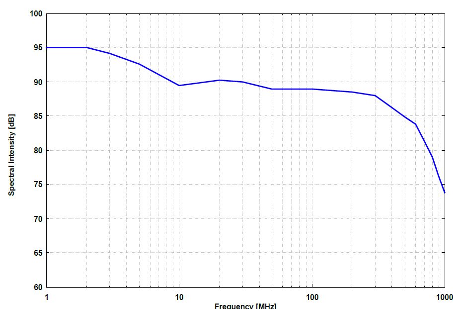
As a result of this principle the output spectrum is very constant and there is enough amplitude even at low pulse frequencies. Low pulse frequencies must be used when narrow spaced spectral lines are needed to recognise narrow band resonance or notches.
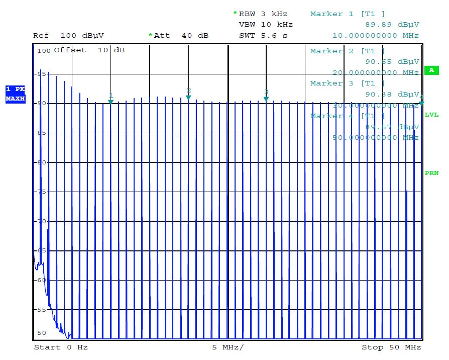
The frequency spectrum can be measured precisely using an EMI receiver.
The result of this measurement combined with the antenna data can be used to calculate the field strength. An example how to calculate the field strength is given at the end of this manual.
The built-in NiMH-battery keeps the generator working for about 10 hours and can be charged in a short time with the automatic charger ACS 110 traveller. A green LED shows readiness for operation.
Calculating example
Using the SG 9301 and the small biconical antenna UBAA 9114 with BBUK 9139 elements we want to generate a field (reference radiator). The free-space field strength at 30 MHz in a distance of 3 m is wanted. This can be calculated like this:
F [dBμV/m] = -2.2 + gi [dBi] + U [dBμV] - 20 log D [m]
Field strength Level: F [dBμV/m]
The isotropic gain of the transmit antenna: gi [dBi]
Voltage at antenna input under perfect matching conditions: U [dBμV]
Using the voltage from the table above at 30 MHz and the gain of the antenna (from datasheet) of -38.24 dBi and the distance of 3 m we get:
F = -2.2 -38.24 + 90.0 – 9.54
F = 40.02 dBμV/m
Biconical antennas usually have a very high VSWR in the lower frequency range. Conditions of perfect impedance matching are thus not applicable. Standing waves might cause measurement uncertainty. Forced impedance matching by using an attenuator like DGA 9552 N 10 dB between the SG 9301 and the antenna may be a way to eliminate standing waves. This works only if the generated field strengths show sufficient S/N. The measured field strength should be at least 10 dB higher than the noise floor of the system. The distance to the noise floor can be improved by using a Tx antenna with a better gain, e.g. a larger biconical antenna like VHBB 9124 with BBA 9106 elements. Using this antenna instead of the small UBAA 9114 with BBUK 9139 will lead to 24 dB higher field strength levels.
|
OTHER PRODUCTS IN THE SAME CATEGORY:
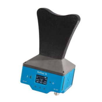
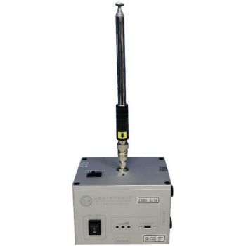
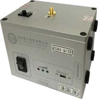
CG01-5, 5 MHz - 1 GHz, 5 MHz Steps, Comb Generator
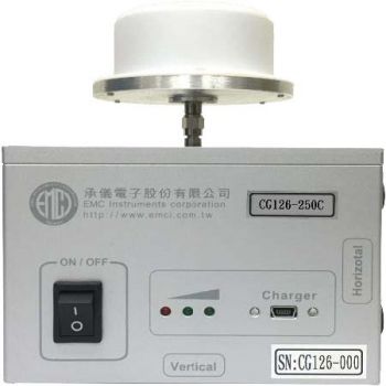
CG126-250C, 250 MHz - 26.5 (40) GHz, 250 MHz Steps, Comb Generator
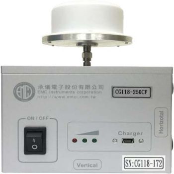
CG118-250CF, 1 GHz - 18 GHz, 250 MHz Steps, Comb Generator
CG 100/500, 100 kHz - 400 MHz, 100 and 500 kHz Steps, Conducted Comb Generator
CG 50/500R, 50kHz - 30MHz, 500kHz Step, Comb Generator
CG08-100R, 100 MHz - 7.5 GHz, 100MHz Step, Comb Generator
CG08-10/100R, 10 MHz - 8 GHz, 10 & 100MHz Step, Comb Generator
CG118-100CF, 100 MHz - 18 GHz, 100 MHz Steps, Comb Generator
CG 10/500, 10 kHz - 30 MHz, 10 and 500 kHz Steps, Conducted Comb Generator
CG 50L/510R, 50 kHz - 1 GHz, 50/500kHz & 5/10MHz Steps, Conducted & Radiated Comb Generator

CG140-1000C, 1 GHz - 40 GHz, 1 GHz Steps, Comb Generator
CG01-10, 10 MHz - 1 GHz, 10 MHz Steps, Comb Generator
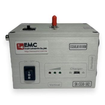
CG 50LR10100R, 50kHz/500kHz - 108MHz for LISN & 10MHz ~6GHz for RE, Comb Generator
CG 50/500LLA, 50 kHz - 30 MHz, 50 and 500 kHz Steps, Conducted Comb Generator
CG 10L10100R, 10 kHz - 100MHz, 10/500kHz 10MHz/100MHz Steps, Conducted & Radiated Comb Generator
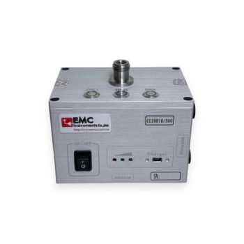
CG 20H10/500 Conducted Comb Generator, 20Hz/30MHz, 20Hz/500kHz Steps

CG-100L10100R, 100 kHz - 7.5GHz, 100/500kHz & 10MHz/100MHz Steps, Conducted & Radiated Comb Generato
CG-50LR10100R, 50 kHz - 6GHz, 50/500kHz 10MHz/100MHz Steps, Conducted & Radiated Comb Generator (Dup
CG01-025, 25 MHz - 6 GHz, 25MHz Steps, Comb Generator

