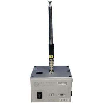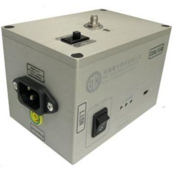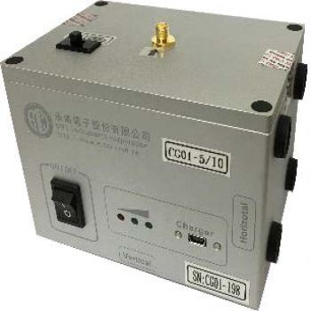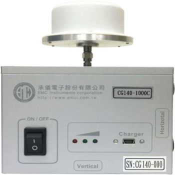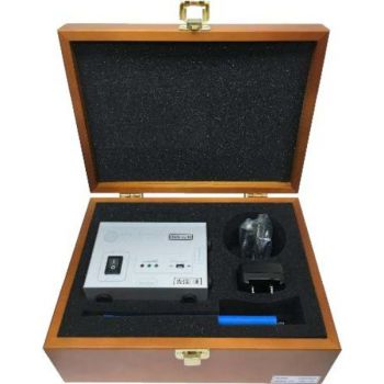
IGUF 2910 S, High Power Pulse Generator
- Small battery-operated generator
- Works with all appropriate antennas via 50 - Ohms - Output
- Standard field generation without problems caused by cables
- Easy receiver tuning due to broadband-spectrum
- High pulse repetition frequency gives audible sound
- Extremely high pulse power: 1.8 kilowatts at 50 Ohms
- Exceptionally flat spectrum: 300 MHz / - 1 dB, 1 GHz / -6 dB
IGUF 2910 S, High Power Pulse GeneratorThis High Power Pulse Generator operates in a similar way as our calibration generators IGUU 2916 and IGUU 21918 which are used as a standard worldwide. In these generators, a coaxial line is charged using a high voltage dc source. The charge in the line is then discharged into the load via a relay contact. The relay contact combines the best ON / OFF resistance and bouncing behavior.
The dc - voltage is precisely stabilized. Due to the simplicity of the design, parasitic side effects sometimes mentioned with semiconductors do not occur. The built-in chargeable battery permits the use of the generator directly on the antenna connector without the necessity to use a cable. The 50 - Ohm - output-connector (N-type) and the high output power gives an easy measurement of site attenuation. A variety of suitable antennas may be connected from precision dipoles to Logbicon broadband antennas.
IGUF 2910 S Technical Data
Setup: The mechanical relay contact used in the IGUF 2910 S operates best in a vertical position. So please keep the generator in a vertical position (+-30° inclination). The writing on the front panel must be upright in a horizontal position. If the generator is turned out of the vertical position, it stops generating pulses. Back in the vertical position, it will resume its work again without any damage. The IGUF may also be fixed to the antenna connector via an attenuator.
Operation: The generator is very simple and the operation is practically self-explaining. Switch it ON by shifting the ON/OFF switch in the right position. When the generator is in the correct vertical position, a low humming noise can be heard with a frequency of approx. 250 Hz. It is caused by the switching relay. Remarks: This humming noise will also be heard in the receiver. It can easily be discriminated from other signals (broadcast) Sometimes noise may become a little bit "fuzzy". This is caused by minor "bouncing" of the relay contact. This effect doesn't affect the quality of the measurement. The output connector (N-socket) may be connected to the load directly or via an attenuator. Practically all kinds of generators show deviations in output impedance when operated at their maximum output voltage level. For most applications, it is therefore recommended to use an attenuator. By that, an incorrect load impedance leads only to a predictable mismatch (i. e. mismatch of the load). With a perfect load, the attenuator is not needed. Feeding antennas or absorbing clamps as a load always require an attenuator. Receivers are always in danger because of the high output voltage of the generator. |


