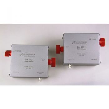
BN 1701, Buffer network (discontinued)
Buffer network (CISPR 17)
Frequency range: 100 kHz - 30 MHz
max. 32 A

SPECIFICATIONS
BN 1701, Buffer network (discontinued)CISPR 17 describes Methods of measurement of the suppression characteristics of passive EMC filtering devices. The following three methods are mainly applied:
Since EMC Suppression Filters do not come with coaxial connections there is a need for suitable measurement equipment to obtain reliable measurements. The international standard CISPR 17 includes several methods and measuring equipment which is useful to compare EMI suppression parts among each other and allows an efficient selection of appropriate EMI suppressor devices. The MIL-STD-220 includes also methods to measure the insertion loss of passive EMI filters.
Especially when measuring filters coupling networks (so-called buffer networks) are required which are able to apply the current that occurs during regular operation to the device under test. Nevertheless, the buffer network may not influence the measurement and it is supposed to protect the measuring equipment from getting damaged by the test current injected. Usually, it is required to connect one buffer network each to the input and to the output of the device under test. The networks consist of L/C high pass filters. Sometimes these buffer networks are called “BIAS Tee” or “DC BIAS” as well. Within the standard CISPR 17, you can find the principle schematic in figure 1 in annex D. C1 decouples the DuT from the generator respectively from the level meter. Its impedance has to be small in proportion to the system impedance especially at low frequencies and it must not show disturbing self-resonances. The inductor L1 provides the current from the load source to the device under test The impedance of the coil has to be big enough within the frequency range of the test set-up to prevent the measurement result from being distorted. The capacitor C2 blocks RF from the load source.
|
OTHER PRODUCTS IN THE SAME CATEGORY:
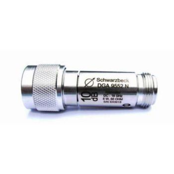
DGA 9552 N, Attenuator, 5 watts, 18GHz, 3, 6, 10, 20, 30, & 40dB
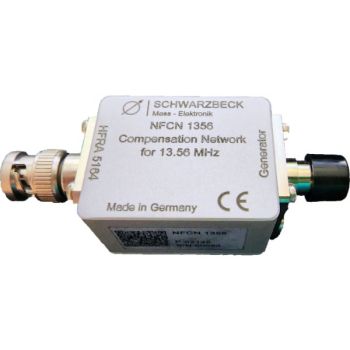
NFCN 1356, 1356 kHz Compensation Network for HFRA 5164
NFCN 9734 - DC- 200 kHz Compensation Network
NFCN 9731-100, DC- 180 Hz Compensation Network for HHS 5230-100
NFCN 9732-85, 80 - 90 kHz Compensation Network for HHS 5206-8
NFCN 9732-120, 50-60 Hz, Compensation Network for HHS 5210-100
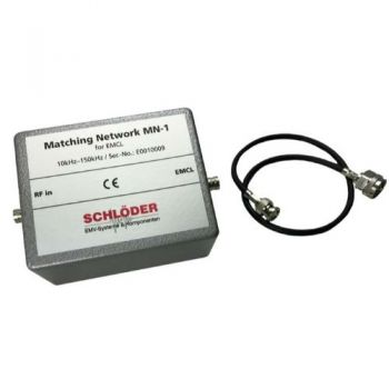
CDG EMCL- NW 10 / MN-1 EM Clamp Matching Network
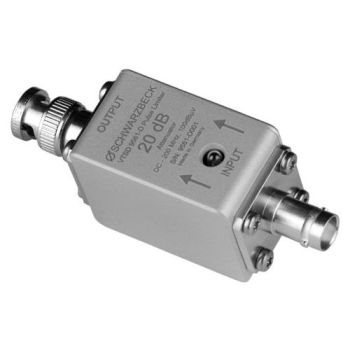
VTSD 9561 D, 20dB, Diode Pulse Limiter
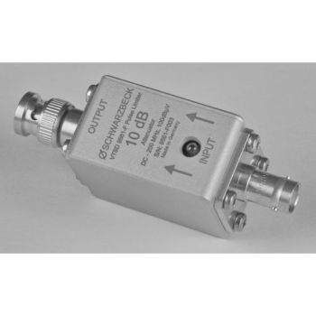
VTSD 9561 F, 10dB, Diode Pulse Limiter
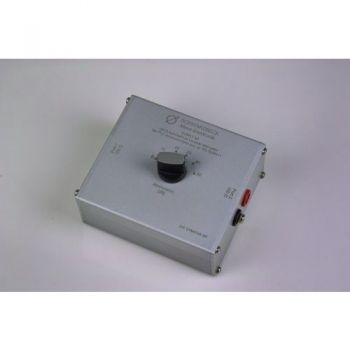
SYMAT 40, Symmetrical Step Attenuator, 100 Ohms acc. EN 50561-1
BN 1701, Buffer network (discontinued)
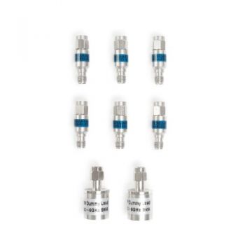
TBAS2 SMA Attenuator & Terminatation Set
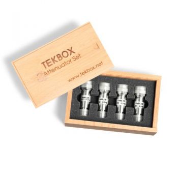
TBAS1 RF Attenuator Set
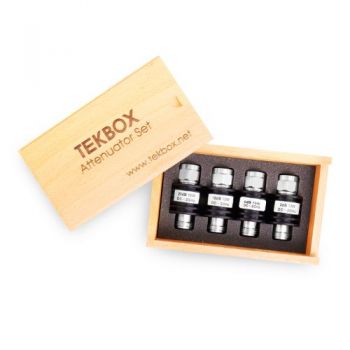
TBAS3 10W Type N Attenuator Set
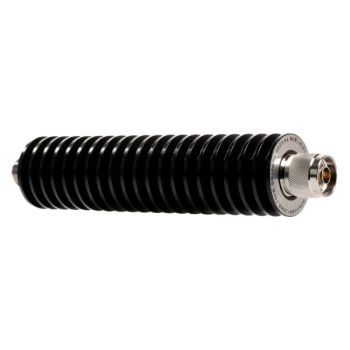
TBATT 10-100W, 3-30dB Attenuators
TBTER-50 Ohm RF Terminations
TBFL1 - Transient Limiter
EMCI-BSF Boresight Fixture
LS Fiber Connector Cleaning Kit

