PGA 1241 & PGA 1330 Comm.Mode -4-16, Diff.Mode -4-19
For EMC tests according to the standard IEC/ EN 61000-4-16, -19 and IEC/ EN 61543
- Common Mode & Differential Mode
- Power module with 5A / 250 W or 16A / 800 W
- Signal generator with DC, sine, triangle, and square waveforms
- The external source can be added to the internal signal
- Windows Application software, USB port
PARTNER:
MARKETS:
TEST STANDARDS:

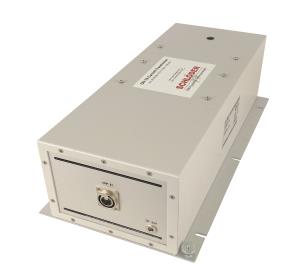
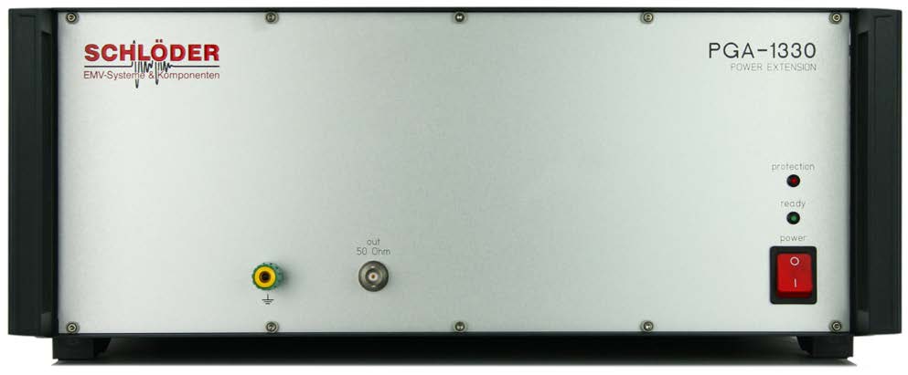
PGA 1330
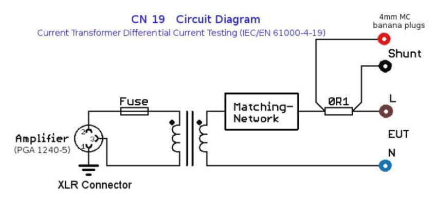
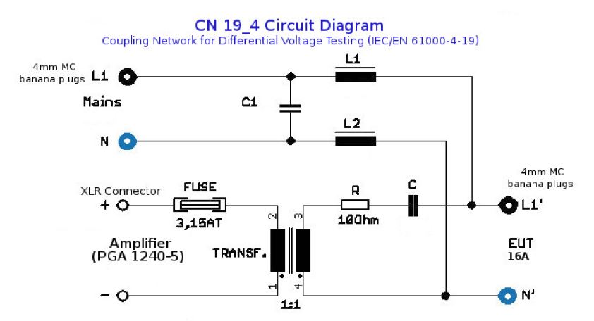
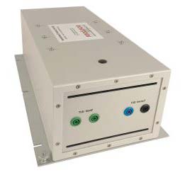
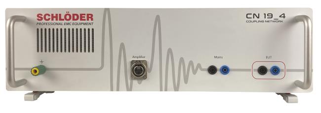
Coupling Network and Current Transformer CN 19, CN 19-4
Coupling Network CN
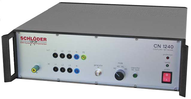
CN 1240 Coupling Network Switch M2-M5
PGA 1241-5A / 1241-16A / 1241-PSG 300
SPECIFICATIONS
PGA 1241-5A, PGA 1241-16A, PGA 1241-PSA 300Precision GeneratorDC – 300 kHz; ±300 V
|
||||||||||||||||||||||||||||||||||||||||||||||||||||||||||||||||||||||
|
||||||||||||||||||||||||||||||||||||||||||||||||||||||||||||||||||||||
Overview |
||||||||||||||||||||||||||||||||||||||||||||||||||||||||||||||||||||||
|
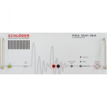
The PGA 1241 is a linear, extremely broadband precision power amplifier for the frequency range from DC to 300 kHz, predestined for all applications requiring fast-changing signals with high power. The power stage with 250 W (800 W) delivers a maximum output current up to 5 A (16 A) with a voltage gain of 10. The integrated function generator supplies sine, triangle, or square wave signals, which are amplified by the built-in power amplifier. External signals can be added via an additional input. All functions of this generator/amplifier combination can be controlled via the application software supplied, which allows complete remote control of the PGA 1241 via the USB interface. The integration into already existing automated test systems is made possible by the disclosure of the interface commands. Key facts
|
||||||||||||||||||||||||||||||||||||||||||||||||||||||||||||||||||||||
Applications |
||||||||||||||||||||||||||||||||||||||||||||||||||||||||||||||||||||||
|
Tests according to IEC / EN 61000-4-16 At 61000-4-16 the PGA 1241 is designed for the continuous disturbance variables (test level 1 to 4 and X to 50V), for the short time disturbance variables up to 300 V the PGA 1331 is required. Both devices can be operated as stand-alone units and integrated into existing test systems. If both continuous disturbance variables and short-term disturbance variables are to be tested, PGA 1241 and PGA 1331 are required and connected together.
|
||||||||||||||||||||||||||||||||||||||||||||||||||||||||||||||||||||||
|
Tests according to IEC / EN 61000-4-19 The PGA 1241 can be used as a test generator for both differential voltage and differential current testing according to IEC / EN 61000-4-19 incl. Appendix C (electricity meter). Since a constant current is required as a disturbing signal and the PGA 1241 generates voltage signals, an external multimeter (which supports SCPI) and an adapter are required for tests according to Appendix C. The multimeter measures the voltage across the adapter, the program calculates the current currently flowing and controls the output of the PGA 1241. |
||||||||||||||||||||||||||||||||||||||||||||||||||||||||||||||||||||||
|
Tests according to IEC / EN 61543 The tests according to IEC/EN 61543 are carried out in the frequency band from 1 kHz to 150 kHz and require a constant current as an interference signal. The PGA 1241 generates a voltage signal and therefore requires an additional multimeter and adapter to meet the requirements of the IEC/EN 61543 standard. The multimeter measures the voltage and the program of the PGA 1241 calculates the current and readjusts the voltage.
|
||||||||||||||||||||||||||||||||||||||||||||||||||||||||||||||||||||||
General applicationsThe generation and amplification of small signals to produce larger output signals is a necessary practice in all areas of electrical engineering. The PGA 1240 is the ideal instrument for this. Due to the excellent signal quality and the remote control via USB interface, the PGA 1241 is the ideal choice for automatic test equipment.
Low resistance loads The PGA 1241 is ideally suited for operation with low impedance loads (e.g. Helmholtz coils). The possible halving of the operating voltage reduces the power loss accordingly. Waveform The generator of the PGA 1241 provides 3 different waveforms: sine, triangle, and square. The frequency resolution is 0.05 Hz from DC to 300 kHz. With all waveforms, it is possible to superimpose a common-mode voltage. Technology A completely linear circuit design guarantees the lowest distortion, noise-free operation, and high stability. Two different operating voltages optimize power dissipation with low impedance loads. Safety devices The tests according to IEC/EN 61543 are carried out in the frequency band from 1 kHz to 150 kHz and require a constant current as an interference signal. Software control The scope of delivery includes application software that enables complete remote control of the PGA 1241 via the USB interface. Integration into existing automated test systems is made possible by disclosing the interface commands. The amplifier can be configured so that it automatically switches on again after a pre-programmed time (1 - 255 s) in the event of power loss or overcurrent shutdown.
|
||||||||||||||||||||||||||||||||||||||||||||||||||||||||||||||||||||||
|
|
||||||||||||||||||||||||||||||||||||||||||||||||||||||||||||||||||||||
|
|
||||||||||||||||||||||||||||||||||||||||||||||||||||||||||||||||||||||
|
||||||||||||||||||||||||||||||||||||||||||||||||||||||||||||||||||||||
|
PGA 1241-PSG 300: Option: External voltage source, input for controlling an external voltage source. 50 Ohm output, for short-term tests up to 300 V Option instead of PGA 1331.
Included in delivery
Options: Isolating transformers (according to EN 61558)
Options: Coupling network Coupling network acc. to EN 61000-4-16
Coupling network acc. to IEC 60255-26 / ITU-T
|
||||||||||||||||||||||||||||||||||||||||||||||||||||||||||||||||||||||
OTHER PRODUCTS IN THE SAME CATEGORY:
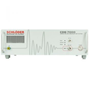
CDG 7000 Conducted Immunity, 10 kHz - 400MHz
CDG 7000-E Conducted Immunity Generator, (4)9 kHz - 1 GHz , No internal Amplifier
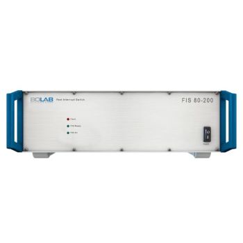
FIS 100-200 Fast Interrupt Switch 100V/200Amps
CDG 7000-75-10 Magnetic & Conducted Immunity, 10 kHz - 250MHz

400 - 6112, 2-Ch, 250kS/s, AnyWave Control Unit
400 - 6361, 2-Ch, 2.8MS/s, AnyWave Control Unit
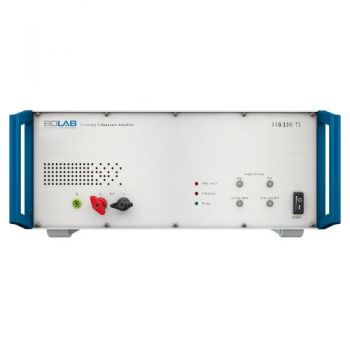
100-TS, 4-Quadrant Voltage Amplifiers 400 W - 54,000 W
100-TS, 4-Quadrant Current Amplifiers 400 W - 54,000 W

AN-ABCD-300, 300 Amp Artificial Network, EV HV Testing

AN-ABCD-60, 60 Amp Artificial Network, EV HV Testing
100-TS, VW 80000 / LV 124 : Battery test systems Test systems for 12 V | 24 V | 48 V batteries

100-TS, VW 80300 / LV 123 / LV 148 : HV Electric vehicle test systems
PGA 1241 & PGA 1330 Comm.Mode -4-16, Diff.Mode -4-19
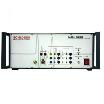
MGA 1033; Magnetic Immunity DC-250 kHz, 800 Watts
60-1C, 0-60V, 9-2000+kW, DC Power Supply, Sink/Source
80-1C, 0-80V, 9-2000+kW, DC Power Supply, Sink/Source
160-1C, 0-160V, 18-2000+kW, DC Power Supply, Sink/Source
240-1C, 0-240V, 27-2000+kW, DC Power Supply, Sink/Source
320-1C, 0-320V, 36-2000+kW, DC Power Supply, Sink/Source

