HXYZ 9170 - CISPR 15 3-dimensional loop antenna van Veen
- Loop Antenna System ( LAS )
- 3-dimensional large loop antenna
- diam. 2 m
- acc. EN 55015 / CISPR 15
- Socket and Coaxial switch recommended
PARTNER:
MARKETS:
CATEGORIES:
TEST STANDARDS:

Data Sheet
Stand Data Sheet
Switchbox Control Data Sheet
SPECIFICATIONS
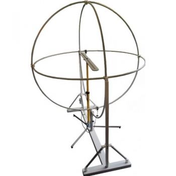
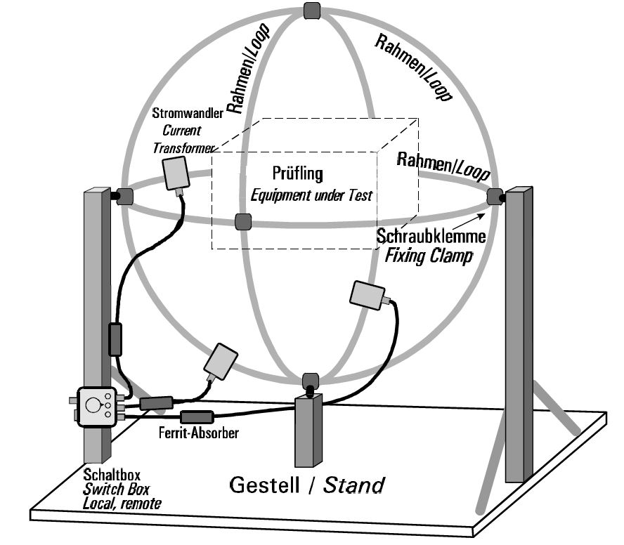
HXYZ 9170 Triple Loop AntennaAccording to EN 55015 / 4.4, the magnetic field strength of fluorescent lighting luminaires has to be measured if the operating frequency is above 100 Hz. The measurement is done with a triple loop antenna as shown above. The Unit Under Test is positioned under operating conditions in the center of the triple loop antenna. To measure the magnetic field strength without turning, there are loops in X-,Y- and Z-direction. A current transformer converts the loop current into an appropriate voltage. Ferrite chokes reduce braid current on the coaxial cables which would cause the wrong measurement. The switch box gives access to one of the three loops via local or remote control. The r. f.-output is connected to the input of an interference measuring receiver. The calibration balun HFCD 9171 substitutes the E.u.T. during calibration. A signal generator may be used as a source for the balun. An ideal instrument for measurement and calibration is the Schwarzbeck interference measuring receiver FCKL 1528 with the optional tracking generator, which is also the best choice for measuring the insertion loss of luminaires.
Technical Data
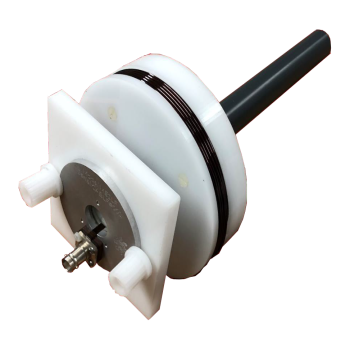
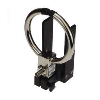
Triple Loop Antenna HXYZ 9170 Principle: Three loops with current transformers acc. to EN 55015 Loop diameter: 2 m Loop Material: PVC-plastic Construction: The three loops are clamped to each other mechanically with plastic clamps on the crossing points. The loops are fixed to a massive ground plate via rectangular glass fiber tubes. Additional struts for best stability and ruggedness. Height: Max. 2,55 m Width: Max. 2,10 m Current transformer: Precision toroid transformer, frequency range 9 kHz-100 MHz in a metal box with BNC-conn.. Ferrite absorbers in 3 coaxial cables.
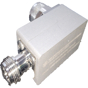
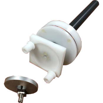
Calibration-Dipole (Balun) HFCD 9171 Principle: Coaxial constant current loop for calibration of the HXYZ 9170 acc. to EN 55015/B.4. Construction: Coaxial cable fixed to a plastic plate. Metal box with BNC-conn.. Switchbox Principle: R.f.-switch to select 1 of 3 loops Control: Manually via a rotary switch, remote control via a 9-pin sub-d-connector 4 LEDs to monitor the state. Attenuation of selected path:<0,5dB 9k-30MHz Leakage from other paths: >45 dB 9 k-30 MHz Construction: Metal box with 4 BNC-connectors and remote control connector. 4 LEDs. The box can be mounted on the glass fiber tube.
Ordering information Basic set HXYZ 9170: 3 loops with current transformers and fixing clamps Stand: HXYZ 9170 Sockel Glass fiber tubes, struts, ground plate. Switchbox: HXYZ 9170 Umschaltbox Selector manual and remote control, 3 coaxial cables with ferrite chokes. Calibration dipole (balun): HFCD 9171, CDA 9271
Options: HXYZ 9170 RS USER Adapter - The HXYZ 9170 - RS adapter is used to connect the switchbox HXYZ 9170 to R&S devices with a 25-pin user interface (e.g. ESPI, ZVR, ESCI, ESCS, FSB).
HXYZ 9170 RS AUX Adapter - The HXYZ 9170 – RS AUX adapter is used to connect the switchbox HXYZ 9170 to R&S devices with a 9-pin AUX interface (e.g. ESL and ESR). |


OTHER PRODUCTS IN THE SAME CATEGORY:
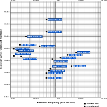
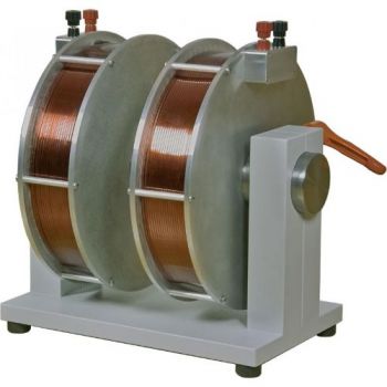
Helmholtz Coils Overview
Coil Set 4-39_9k-150k EN 61000-4-39 & RS101 9kHz - 150kHz, Tx & Rx Set
CAB1356m Coupling Network for 13.56 MHz
CAB134k Coupling Network for 134kHz
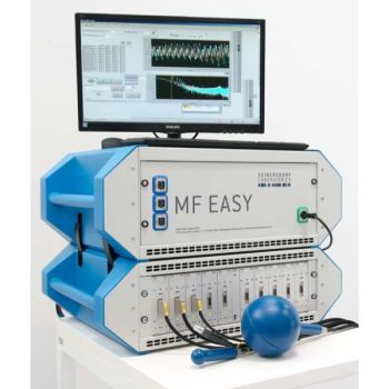
MF EASY, DC-400 kHz, MAGNETIC FIELD EXPOSURE ASSESSMENT SYSTEM
Coil Set 4-39_150k-26M EN 61000-4-39, 150 kHz - 26 MHz, Tx & Rx Set
HFRA 5164, 10 kHz - 120 MHz Transmitting loop antenna
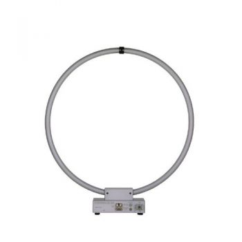
FMZB 1519 C 9kHz-30MHz, Active Receiving Loop Antenna
FMZB 1519-60 D Active Receiving Loop Antenna
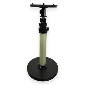
LAS-2000 Loop Antenna Stand
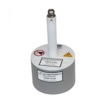
FESP 5139 - DISCONTINUED replaced by HFRA 5164
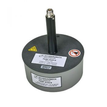
FESP 5133-9 - 10 kHz - 3 MHz Radiating Loop
FESP 5132 - DC - 150 kHz Radiating Loop
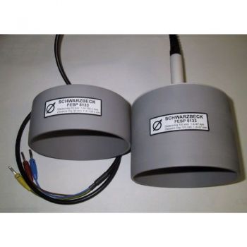
FESP 5133 - DC - 200 kHz Radiating Loop
FESP 5133-1330 - DC - 50 kHz Radiating Loop
FESP 5135 - DC - 300 kHz Radiating Loop
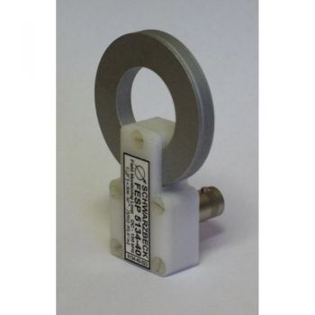
FESP 5134-40 - 5 -250 kHz Circular Screened Coil
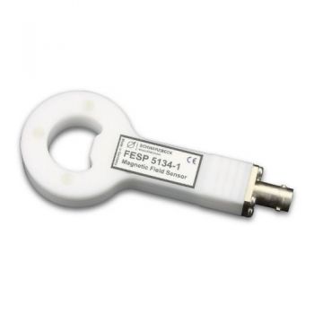
FESP 5134-1 - 10 - 400 MHz Circular Screened Coil
AGEM 5520 - Electromagnet with variable Air Gap

