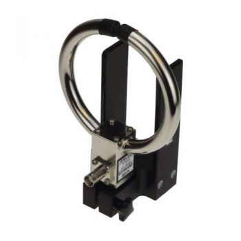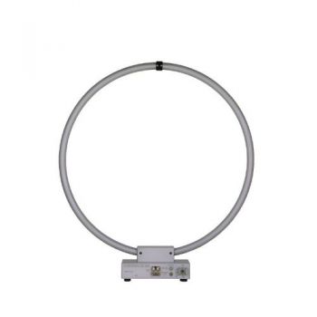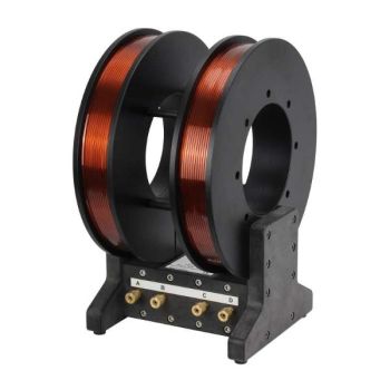
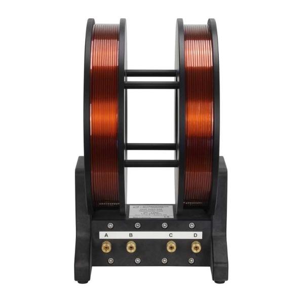
HHS 5203-536 - DC - 2 kHz, Circular Helmholtz Coils
- Circular Helmholtz Coils
- DC - 2 kHz
- Diam.: 256mm
- Turns: 536
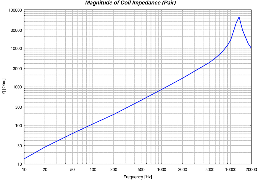
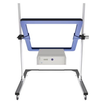
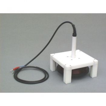
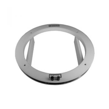
HHS 5203-536 - DC - 2 kHz, Circular Helmholtz CoilsHelmholtz-Coils are designed to generate precisely defined magnetic fields from DC to the middle of the audio frequency range. The generated fields are in a strongly linear relation to the coil current. The field strength can be calculated exactly by analytical (or numerical) methods based on the coils' geometry, the number of turns, and the coil current. Therefore, the HHS 5203-536 is ideally suited for calibrating magnetic field probes or sensors and immunity tests. Due to the high temperature-proof coated copper wire packet, it can generate magnetic fields up to more than 40 kA/m (for a short time). Typical applications are magnetic immunity testing according to automotive standards or MIL STD 461. The coil current is directly proportional to the magnetic field strength when generating magnetic fields with Helmholtz coils. The calibration of the magnetic field is finally traceable to a current measurement (or to a voltage drop at a known resistor). The Helmholtz Coil itself is usually considered the primary standard due to the easily calculable relation between current and field strength. If this relation should be controlled, a loop sensor or monitoring loop can be used to determine the actual field strength. Specifications:
Installation:
Field strength determination:
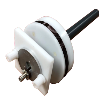
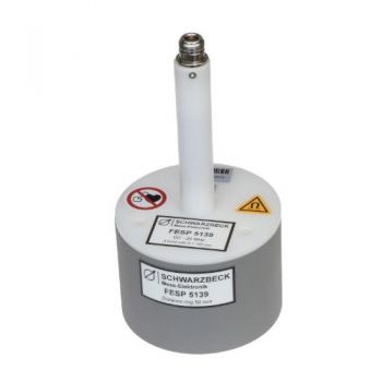
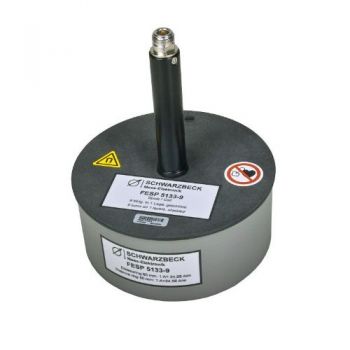
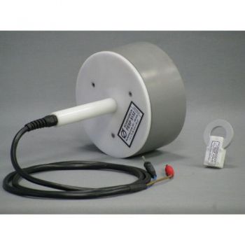
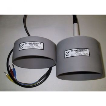
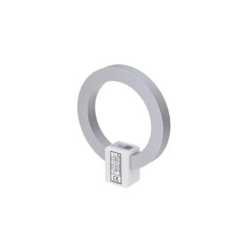
There are two methods to determine the actual magnetic field strength: 1. Determination of the coil current • Current transformer clamp, • Measuring the voltage drop across a wellknown resistor, • Direct current measurement. 2. Determination of the field strength using a field monitoring loop. The direct current measurement has the disadvantage that the measurement equipment itself heats up, which leads to increased measurement uncertainty or even destruction. The use of a calibrated current transformer clamp has two advantages: it is floating (potential isolation between measuring circuitry and amplifier output circuitry) and without thermal stress. In cases where the voltage drop across a known resistor (e.g., 100 m? / 20 W up to 14 A or 10 m? for highest currents) is measured, it is essential to provide sufficient cooling and potential isolation of mains-driven voltmeters. Using small shunt resistor values causes less heat dissipation and may, however, cause higher measurement uncertainties because the wanted shunt resistance is hardly higher than unwanted contact resistances. Beyond several kHz, the inductance of the shunt resistor may become dominant. For that reason, a low inductive shunt resistor with well-known impedance Z, like the SHUNT 9571, should be used. The determination of the magnetic field strength using a sensor loop (field monitoring loop) also allows potential isolation without temperature stress. The FESP 5133-7/41 or the FESP 5134-40 are suitable for this purpose. |


