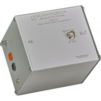
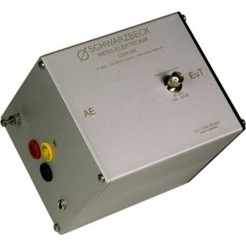
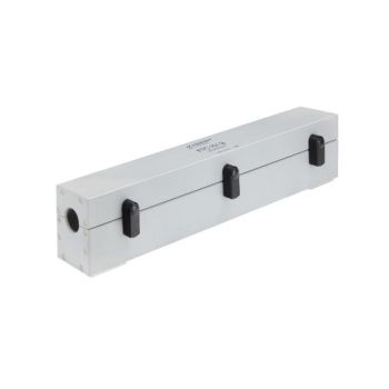
CDNE M2, 2 lines, Coupling & Decoupling Network, CISPR 15
- for testing 2 line mains (without PE)
- Also works as CDNE AF2
- CISPR 15, EN 55015
- 30 MHz - 300 MHz
PARTNER:
MARKETS:
CATEGORIES:
TEST STANDARDS:

Data Sheet
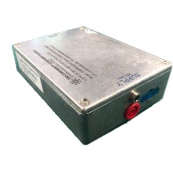
SR100-6W B Data Sheet
SPECIFICATIONS
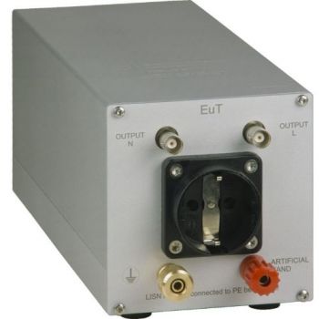
CDNE M2, 2 lines, Coupling & Decoupling Network, CISPR 15CDNs have been used as coupling- /decoupling networks to measure conducted noise as well as for immunity testing so far. Contrary to the couple-/decouple networks (CDN) described in IEC/EN 61000-4-6 the category of CDNE has been created especially for the measurement of emissions of luminaries featuring tighter tolerance.
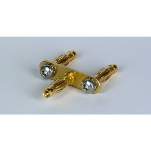
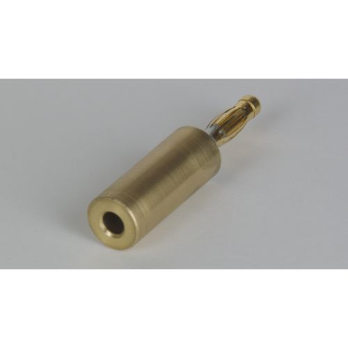
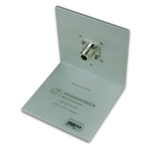
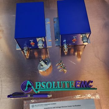
! Attention! The CDNE is not appropriate for measuring immunity! Details regarding this topic are described in EN 55015. The tolerances of the asymmetric impedance became tighter. The tolerance for the voltage division factor is now defined constantly over the whole frequency range and a new requirement for a defined symmetrical impedance has been introduced for the frequency range 30 MHz to 300 MHz. For measurements on DuTs without PE one has to use the CDNE M2. For measurements using PE, N, and L the CDNE M3 has to be used. The interference voltage emitted by the device under test can be measured at the BNC jack of the measurement port. The voltage division factor to this port is 20 dB. Due to the current-compensated coils within the CDNE it is ensured that there is a minimum decoupling of at least 30 dB between EuT and AE. Noise coming from the mains side is thus well kept away for the measurement. The connection to the ground can be accomplished using the ground plane of the CDNE. Additionally, there is an M4 thread located at the AE side to the ground as well as a 4 mm socket to connect the device to the ground. To improve operational safety the mains voltage-carrying connections are carried out as security sockets. We recommend using special 4 mm security plugs if you plan to design your own adapters. Those connectors can be purchased optionally. To verify the CDNE some measurements require a common mode potential. The common-mode reference point is defined for CDNE devices for unshielded cables as the short-circuiting point of all wires. To be able to measure at the hereinbefore mentioned point to check the standard values of the CDNE (i.e. common-mode impedance, voltage division factor) a low-inductance and low-resistance short circuit jumper are required. This adapter is available optionally. It consists of two parts. There is a shortcircuit bridge (CA CDNE M2 Part A) One of the most important characteristics of the CDNE is the coupling attenuation between the EuT port and the BNC measurement port (other expressions: correction or Voltage Division Factor VDF). This attenuation is recorded for each device and is part of the calibration certificate. If the coupling attenuation is supposed to be calibrated in the real emission measurement setup a serial the resistance of 100 Ω is needed to adapt the 150 Ω of the CDNE to the 50Ω measurement system. For this purpose, we offer the optionally available adapter SR100-6W.
There is a resistive attenuator built in the BNC output to force a match. According to the standard CISPR/A/944/CD Fig. J2 a value bigger than 6 dB is demanded. By design, the internal circuit has an attenuation of 9.5 dB. Together with the built-in attenuator of 10.5 dB, this results in a total attenuation of 20 dB. Thus the measurement port matches the 50 Ohm very well and supersedes an external attenuator.
|
 and an adapter kit (CA CDNE Part B)
 .
.
OTHER PRODUCTS IN THE SAME CATEGORY:
CDNE M2, 2 lines, Coupling & Decoupling Network, CISPR 15

SR100-6W, adaptor 150 Ohm to 50 Ohm, 100 Ohm resistor

AN-ABCD-300, 300 Amp Artificial Network, EV HV Testing

AN-ABCD-60, 60 Amp Artificial Network, EV HV Testing
CABCISPR2532A, CISPR 25, 5uH, 32 A LISN
CABCISPR2515A, CISPR 25, 5uH, 15 A LISN
Cx 10000-xxx-xxx, 1000V, 100 - 600 amp 10mF HV Capacitor Cabinet
NSLK 8117, 9 kHz - 30 MHz, 250V / 10A, 50 µH, 2 Path LISN
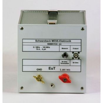
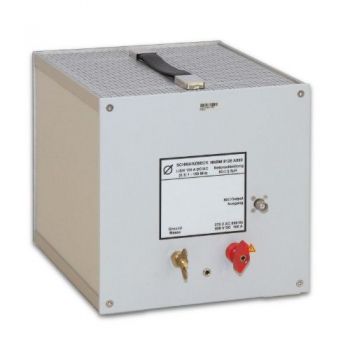
NNBM 8124, 10 kHz - 150(400) MHz, High Voltage, 70A, single path, 5µH LISN
MDS 21 C, 30 - 1000 MHz, EMI Absorbing Clamp
EMCL 6146, 10 - 1000 MHz, EM Coupling Clamp and CAL EMCL Cal Fixture
FTC 101 B Decoupling Clamp
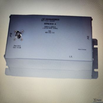
NTFM 8131 A, ISN for 2 unshielded Unsymetrical lines, Acc CISPR 32
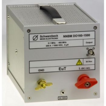
NNBM DO160-1500, 10 kHz - 400 MHz, 200A, 5µH LISN, DO-160
NNBM 8126 A890, 10 kHz - 400 MHz, 75A, 5µH LISN, DO-160
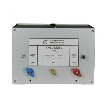
NNBL 8226-2, 9 kHz - 100 MHz, 70A, 50µH, Two Path LISN
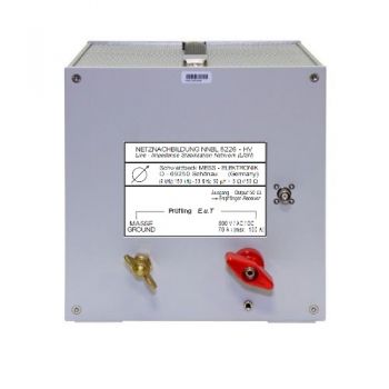
NNBL 8226-HV, 9 kHz - 100 MHz, 70A, 50µH, Single Path LISN
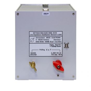
NNBL 8226, 9 kHz - 100 MHz, 70A, 50µH, Single Path LISN
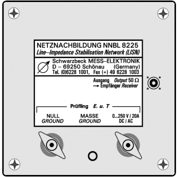
NNBL 8225, 9 kHz - 100 MHz, 20A, 50µH, Single Path LISN

