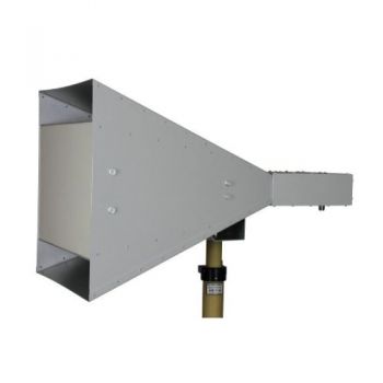
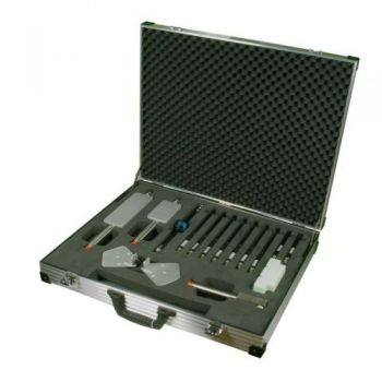
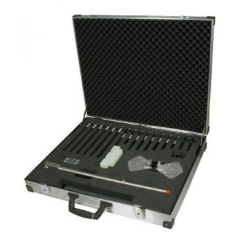
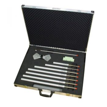
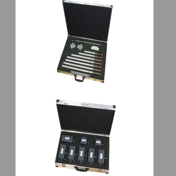
BBV 9718 D & BBHA 9120 D Kit, 1 - 18 GHz, Horn Antenna & Preamp System
- 1-18 GHz Horn antenna + Preamp
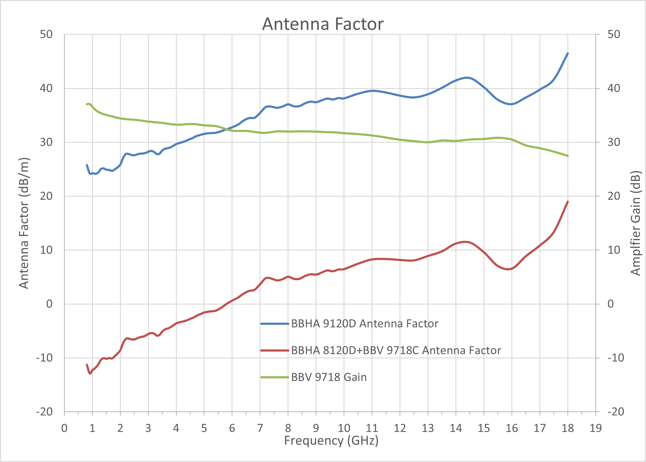
- 30dB Gain
- Excellent Matching and ease of use
- Battery Operated CHarges through USB charger included

Data Sheet
Data Sheet BBHA 9120D
SPECIFICATIONS
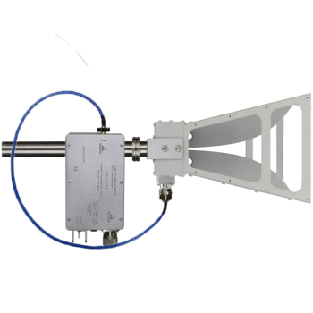
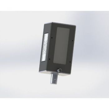
BBV 9718 D & BBHA 9120 D Kit, 1 - 18 GHz, Horn Antenna & Preamp SystemThe BBV 9718 D is a low noise low power wideband preamplifier to increase sensitivity during field strength-measurements and for general attenuation measurements up to 20 GHz.
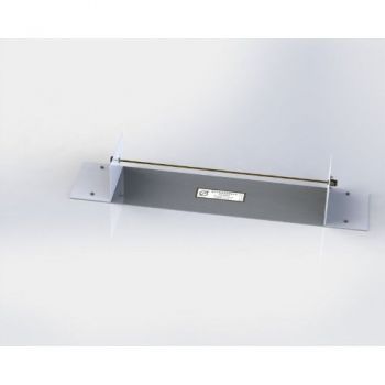
Including short cable with Type N to SMA plugs to connect the BBV 9718 D with the antenna (for example BBHA 9120 D, STLP 9
148, or ESLP 9145). The charger is Included.
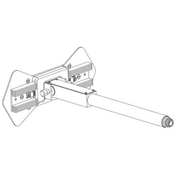
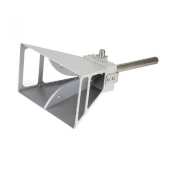
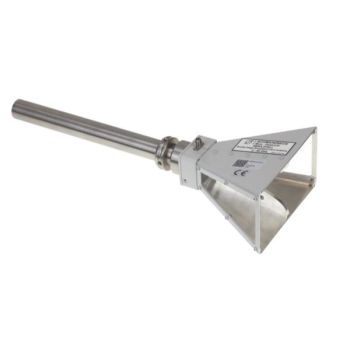
The amplifier Input comes with an SMA female connector. A coaxial microwave cable of 0.5 m length is supplied to connect the Antenna with the Amplifier. The cable is equipped with N-male and SMA male connectors. Usually, the amplifier should be installed very close to the antenna. The Amplifier Housing is equipped with rubber pads for placement on horizontal surfaces. Further, there are 22 mm holes in the housing to accept the mounting tube of Schwarzbeck-Antennas. The antenna mounting tube is usually oriented horizontally with the N-female output of the amplifier facing to ground. This avoids undesired bending of the coaxial cable.
Beginning of operationOperation environment The BBV 9718 is preferably used indoors. While using on open area test sites, it must be protected from weather conditions, especially humidity. Switching ON The device is turned on with the pilot- style power-switch. Push the switch to the upper side. The green LED “On” indicates the proper charged battery. The red LED “Low Bat” means the battery is nearly empty. If the LED is dark even while the generator is turned on the rechargeable battery is disconnected because of low voltage. After charging the unit will be ready for operation. More Information about Battery The BBV 9718 is equipped with a 3.7 V Lithium cell. The battery voltage is indicated with a green LED for normal operation. If the red LED “Low Bat” is illuminated recharge is required. A full battery charging period using the USB port takes around 6 hours. While recharging the yellow LED “Charge” is illuminated. The power-switch should be set to OFF during the recharging period. It is possible to measure during recharging. But disturbances generated by the charger could have an unwanted influence on the measurement. A special circuit prevents the battery from being discharged completely. Whenever the voltage is too low for battery health or measurement precision, it will be automatically disconnected from the load. When the BBV 9718 is switched ON and the red LED below is dark, this isolation has taken place. In this case the battery must be charged immediately. The second best advice is to switch OFF the BBV 9718 to avoid the (very low) idle current of the protection ci
Microwave Broadband Amplifier
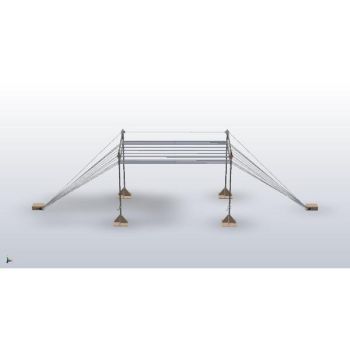
Description:Low Noise Low Power Wideband Amplifier for increasing sensitivity at fieldstrengthmeasurements and for general attenuation measurements up to 18 GHz. Due to the built-in rechargeable battery, operation without power supply is possible for ca. 8h. The amplifier Input comes with an SMAfemale connector. A coaxial microwave cable of 0.5 m length is supplied to connect the Antenna with the Amplifier. The cable is equipped with N-male and SMAmale connectors. Usually the amplifier should be installed very close to the antenna. The Amplifier Housing is equipped with rubber pads for placement on horizontal surfaces. Further there are 22 mm holes in the housing to accept the mounting tube of Schwarzbeck-Antennas. The antenna mounting tube is usually oriented horizontally with the N-female output of the amplifier facing to ground. This avoids undesired bending of the coaxial cable. Typical mounting examples together with Log.-Per. ESLP 9145 with mast Adapter AA 9202 and Mast AM 9144.
BBV 9718 C + 0.5 m Cable N/SMA
SWR BBV9718 C
|


OTHER PRODUCTS IN THE SAME CATEGORY:
BBHA 9120 F - 0.2-2 GHz Double Ridged Horn Antenna
GENE-H-30-3K E/H 10kHz to 30MHz Field Generator / Stripline
BBHA 9120 J - 0.8-6.2 GHz Double Ridged Horn Antenna
SR50 - SR90 ISO 11452-5 Striplines
VPMP 9241- DC -300 MHz, Vertical passive monopole (rod) antenna
RS 9244, Radiation Source, per CISPR 25
419 NJ Elements for NMHC 4MM Balun, Antenna Elements
BBV 9718 D & BBHA 9120 D Kit, 1 - 18 GHz, Horn Antenna & Preamp System
HLC, FAN, EGG, PCD -Compact Dipole/Monopole for Automotive Immunity
VW TL 82166 2016-02 7.3 Antenna Set, 26 MHz - 6 GHz
NMHA 6M Kit, 26 MHz - 2.7 GHz, Normal Mode Tuned Helical Antennas
TSA Kit, 385 MHz - 2 GHz, Tuned Sleeve Antennas
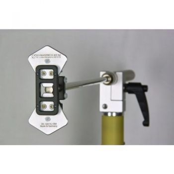
422 NJ Elements for SBA 9119 Small Biconical Microwave Antenna Elements
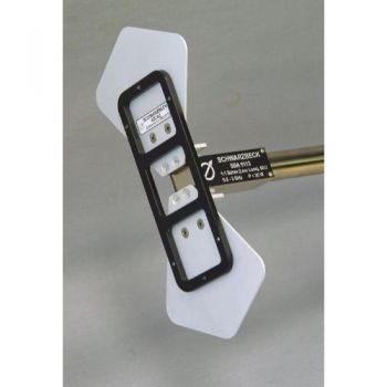
420 NJ Elements for SBA 9113 Small Biconical Microwave Antenna Elements
ISO 11452-9 Set, 26 - 2700 MHz Handy Transmitters
BBHA 9120 K - 0.4-1.6 GHz Double Ridged HiRF Horn Antenna
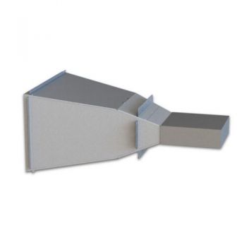
BBHA 9120 D - 1-18 GHz Double Ridged Horn Antenna
BBHA 9120 L - 3-40 GHz Double Ridged Horn Antenna
Antennas Overview Quick Find

