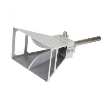
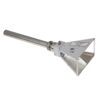
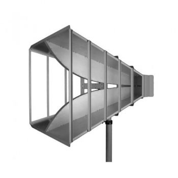
422 NJ Elements for SBA 9119 Small Biconical Microwave Antenna Elements
- Small biconical microwave antenna elements
- 800 MHz - 6 GHz
- Compliant with FMC1278
- Purchase with SBA 9119
- 20 W

Data Sheet
Field Uniformity
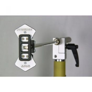
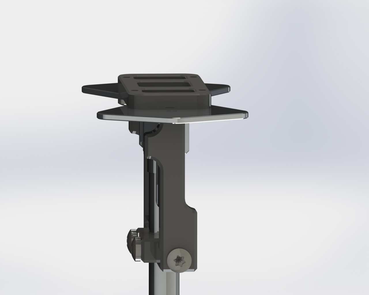
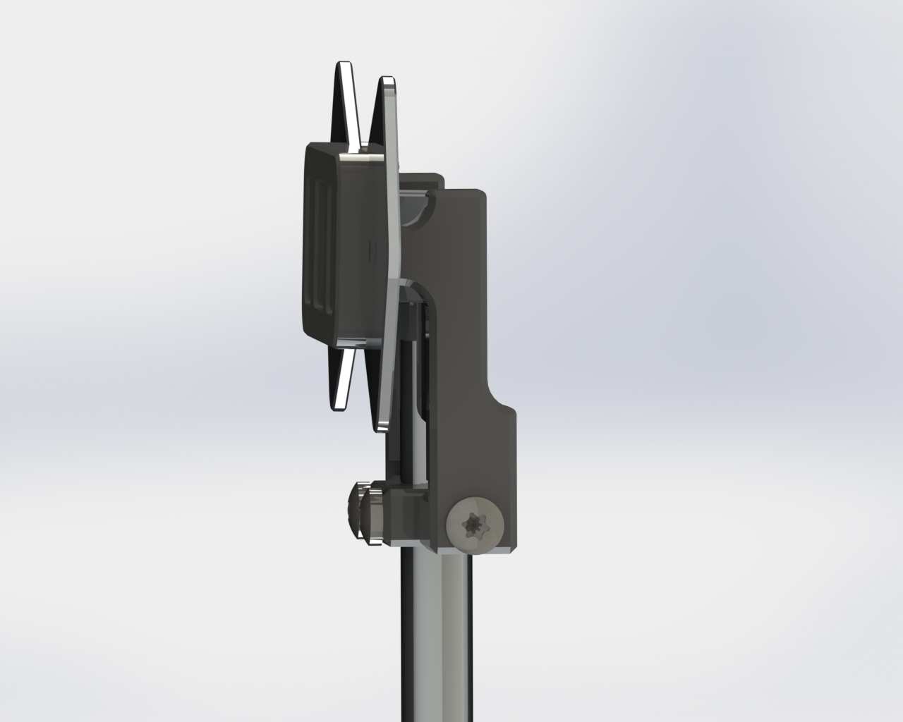
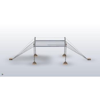
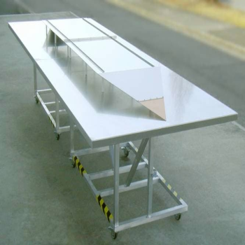
Assembly
SPECIFICATIONS
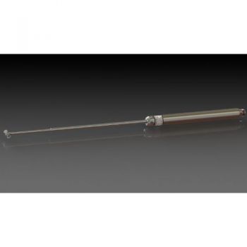
422 NJ Elements for SBA 9119 Small Biconical Microwave Antenna ElementsAfter the very successful introduction of nearfield immunity testing with SBA 9113 and the flat elements 420NJ, a demand for higher frequencies arose. While the 420NJ elements are used from 360 MHz to 2.7 GHz, there are now flat elements available, which cover the frequency range from 800 MHz to 6 GHz. The 422NJ-elements are fed using the balun of the SBA 9119 biconical antenna. Instead of the conical elements, spacer sleeves, and the flat 422NJ-elements elements are used. A high-quality plastic bar is used as a fixation of the flat elements in both ways, parallel and perpendicular to the balun rod. Two knurled nuts are used to connect the radiating elements with the symmetrical feed terminals of the SBA 9119 balun. Further, the elements are equipped with a spacer, which provides a repeatable spacing of 5 mm to the EuT's surface. The change of conical elements to flat ones or vice versa requires only a simple screwdriver and is typically done within two minutes. The flat elements can be arranged perpendicular or parallel to the mounting tube of SBA 9119, depending on the available space in the respective application.
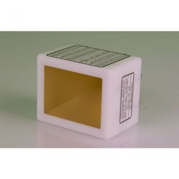
Application:
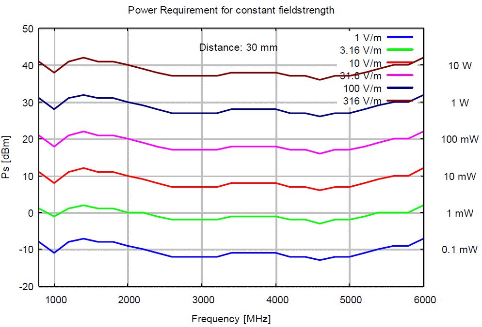
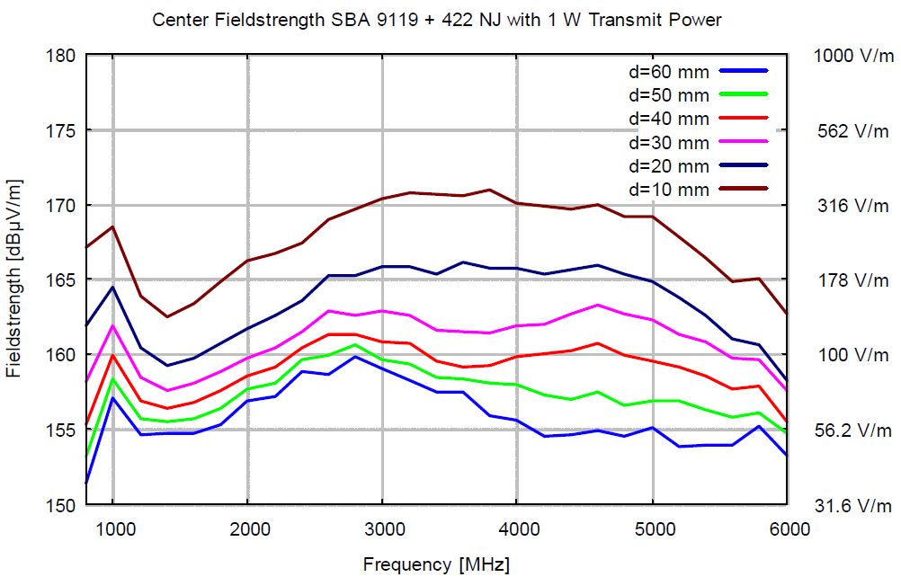
The combination of SBA 9119-Balun with the flat elements 422NJ provides remarkable field-strength levels with moderate transmit power. With 10 Watt transmit power, one can reach field-strength levels of 300 V/m at a distance of 30 mm. This requires only a small adjustment of power over a wide frequency range. The recommended spacing between EuT-surface and 422NJ-elements is 30 mm. This spacing provides both high efficiency and good field uniformity. In most applications, the EuT-surface is divided into a square-shaped mesh, with the mesh width depending on the desired field uniformity. For each mesh crossing, two frequency-swept measurements with orthogonal polarisations are done. This procedure has to be repeated for each remaining mesh crossing until the whole EuT-surface has been covered. Recommended mesh widths are around 30 to 50 mm.
Field Strength
|


OTHER PRODUCTS IN THE SAME CATEGORY:
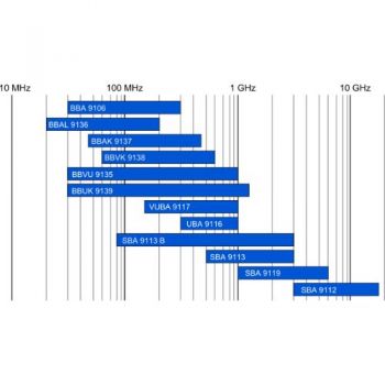
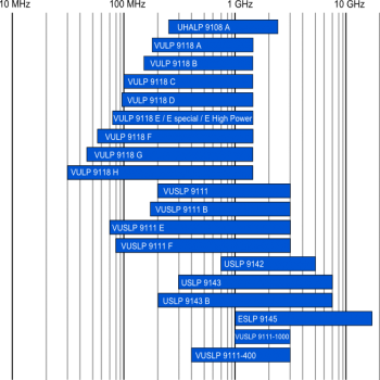
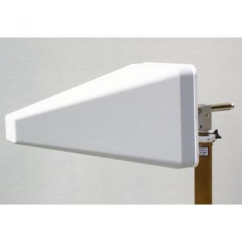
Log Periodic Antenna Overview
BBHA 9120 D - 1-18 GHz Double Ridged Horn Antenna
VULB 9162 - 30MHz - 7GHz TRILOG Broadband Antenna
BBHA 9120 L - 3-40 GHz Double Ridged Horn Antenna
STLP 9129 Sp - 70 MHz - 10 GHz Stacked Log. Periodic Antenna

Antennas Overview Quick Find
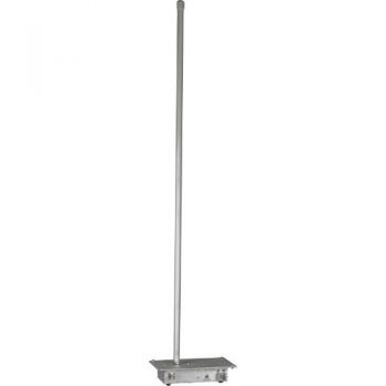
VAMP 9243, 9 kHz - 30 MHz, Vertical Active Rod Antenna
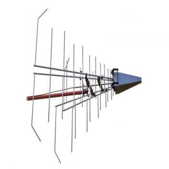
STLP 9129 - 70 MHz - 10 GHz Stacked Log. Periodic Antenna
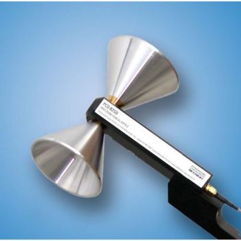
PCD 8250 Precision Conical Dipole 80 MHz – 3 GHz
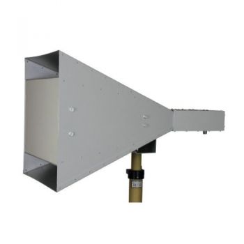
BBHA 9120 J - 0.8-6.2 GHz Double Ridged Horn Antenna
BBHA 9120 F - 0.2-2 GHz Double Ridged Horn Antenna
GENE-H-30-3K E/H 10kHz to 30MHz Field Generator / Stripline
BBHA 9170 - 15-40 GHz Horn Antenna
STLP 9149 - 0.7 - 9 GHz Stacked Log. Periodic Antenna
SBA 9112, 1 to 18 GHz, Small Biconical Microwave Antenna
POD 16 & POD 618 Precision Omnidirectional Dipoles 1 - 18 GHz
PLA-R Receive, Precision Loop Antenna 9 kHz - 30 MHz
PLA-SET for Site Validation, Precision Loop Antenna 9 kHz - 30 MHz
SR50 - SR90 ISO 11452-5 Striplines

