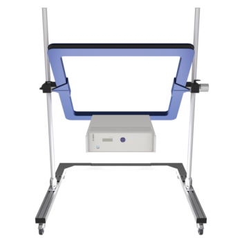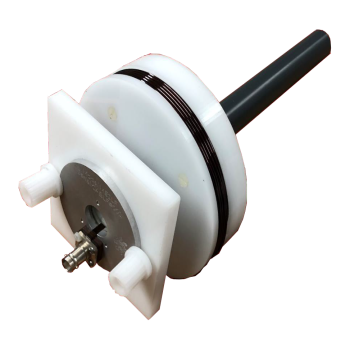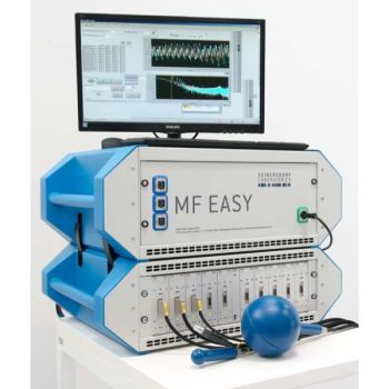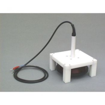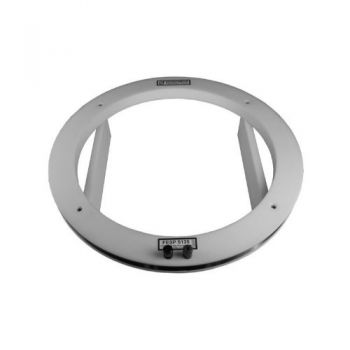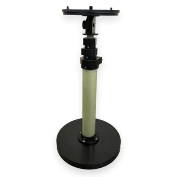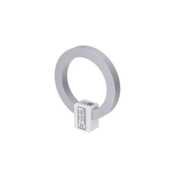
HS 3D-CONTROL
- Display and control for 3D DC Magnectic Field Sensor Head
- Measuring range: typ. max. ± 50mT or 120mT
- 16 Hour battery life
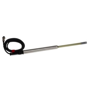
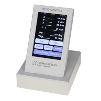
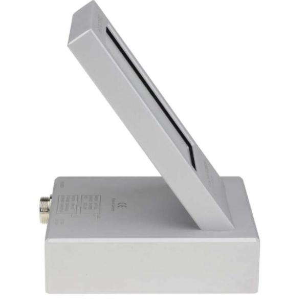
HS 3D-CONTROLThe HS 3D-Control is a display unit that can be used to measure the 3-dimensional magnetic field strength in conjunction with an appropriate sensor (HS 3D-SENS50T1), e.g., to determine the earth's magnetic field. Magnetic field values of the x-, y- and z-axis can be read separately from each other. It is also possible to read the magnitude, inclination and declination directly on the device. The display of the measured values can be set in [μT] or [A/m]. With the help of a Zero-Gauss chamber (e.g. Opt. 5136 ZG) the sensor can be zeroed against the earth's magnetic field. The measured values can be output serially via the USB connection. Depending on the desired measuring range, different sensor heads are available.
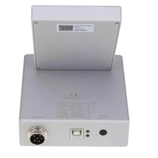
Beginning of operationOperation environmentThe HS 3D-Control is primarily intended for indoor use. When measuring outdoors, it must be protected from all kinds of weather, especially moisture. Switching ONThe unit is switched on with the push button. When the battery is fully charged, the upper LED lights up green, "BAT FULL." If this LED lights up orange, the unit can only be used briefly. If the LED lights up red, charging is urgently required. If the unit cannot be switched on, the internal low-voltage cut-off has switched off the battery. After a new charge, the unit is ready for operation again. In addition, the state of charge is shown in percent in the top right-hand corner of the display, e.g. B100%. More information about the batteryThe HS 3D-Control is equipped with a 3.7 V lithium cell. A complete battery charge via USB takes about 2 hours. During the charging process, the green LED "PWR OK" and the yellow LED "CHARGING" light up. In addition, when the unit is switched on, the active charging is indicated by a C (Charge) in front of the charging status display, e.g. C71%. Deep discharge of the battery is prevented by a protective circuit. If the battery falls below the critical voltage and the measuring accuracy, it is automatically disconnected from the load. This is the case if the HS 3DControl is switched on and the upper red LED does not light up. The battery must then be charged immediately. If the lower LED flashes, the battery system is defective and cannot be charged.
Display
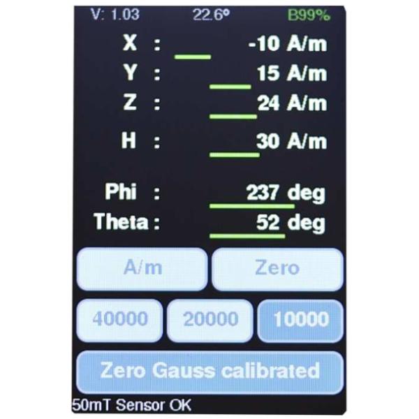
Header:The header shows the software version number on the left, the middle sensor temperature, and the right battery charge level. A “C” before the percentage value of the charge level display indicates that charging is in progress. Otherwise, a B is displayed. Measured values:The values are displayed below. X, Y, Z for the three axes, H for the magnitude of the vector, Phi and Theta correspond to the angle of the magnitude vector. Touch buttons:Below this are 3 rows of touch buttons. If the buttons are pressed, they are displayed in a darker color. In the first row on the left, the unit can be switched between A/m (ampere per meter) and µT (microtesla). The button [Zero] zeros the display. This has nothing to do with the calibration by using the zero-gauss chamber - see the following description. The measuring range can be switched by pressing the buttons in the middle row. Below this is the button for zero gauss calibration. Status bar:Below the buttons is a status line. Here, for example, the sensor type or error messages are displayed.
Start Zero Gauss cal.The button in the bottom row starts the Zero Gauss calibration or switches it off if it is marked as pressed in. If the calibration is started, the content shown below appears next (left picture). The probe should now be inserted as deep as possible into the Zero Gauss chamber. Then, the calibration can be started with the button [Start calibration]. The screen content changes and a bar at the bottom of the screen shows the progress of the calibration process. When the calibration is completed, the results are automatically stored in the flash memory according to the selected measuring range, and the main screen with the measured values appears automatically. Calibration of the sensor is a very important step. It is recommended that the calibration be checked every time the sensor is used in all three measuring ranges and recalibrated if necessary. The sensor is temperature-compensated. However, this only works properly if the zero points have been calibrated correctly. The zero point of the analog-to-digital converter is calibrated, and the temperature compensation is based on this zero point. This is also the difference to the [Zero] key. It does not compensate the zero point of the AD converter, it only subtracts the value measured at the time of pressing the button from the current measured value. This can be used, for example, to compensate the influence of the earth's magnetic field and to measure relative to it. |


