Continuous operation
The nominal coil current is 5 A continuous. The specified nominal magnetic field is 240 A/m continuous. Field values apply at the stated reference spacing.

Precisely defined magnetic fields. DC - 20 kHz.
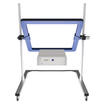
The Schwarzbeck HHS 3D 5213-50 combines three orthogonal coil pairs to generate magnetic vector fields. Each coil has 50 turns, with a usable frequency range from DC to 20 kHz

Data Sheet
Magnetic field strength is proportional to coil current. Coil geometry, the number of turns and the applied current determine the resulting field, allowing the field measurement to be traced to a current measurement or the voltage drop across a known resistor.
The inner Y-axis pair, center X-axis pair and outer Z-axis pair have different coil factors. Their specifications are identified separately below so each axis can be driven for the required field component.
The nominal coil current is 5 A continuous. The specified nominal magnetic field is 240 A/m continuous. Field values apply at the stated reference spacing.
The maximum coil current is 8 A (5 min.). Observe the stated time limit and provide adequate ventilation. The frequency range alone does not imply that maximum current or field is available at every frequency.
Product specifications with reference conditions. See the linked manufacturer datasheet for complete field distributions and operating guidance.
View the complete datasheet →| Number of turns (per Coil) | 50 |
|---|---|
| Maximum Coil Current | 8 A (5 min.) |
| Nominal Coil Current | 5 A continuous |
| Maximum Magnetic Field Strength | 390 A/m |
| Nominal Magnetic Field Strength | 240 A/m continuous |
| Dimensions | 1.4 m x 1.4 m x 1.3 m |
| Frequency Range | DC - 20 kHz |
| Resonant Frequency (per Coil) | > 30 kHz |
| Weight | ca. 85 kg |
| Inner Y-axis — Effective Coil Dimensions | 1.1 m x 1.1 m |
| Inner Y-axis — Coil Separation acc. EN 55103 | 62 cm |
| Inner Y-axis — Magnetic Field Strength, 1 A | 57.7 A/m |
| Inner Y-axis — Resistance (Coil pair) | 3.0 Ω |
| Inner Y-axis — Inductance (Coil pair) | 19.08 mH (Coil Dist. 0.62 m) |
| Center X-axis — Effective Coil Dimensions | 1.21 m x 1.21 m |
| Center X-axis — Coil Separation acc. EN 55103 | 68 cm |
| Center X-axis — Magnetic Field Strength, 1 A | 52.5 A/m |
| Center X-axis — Resistance (Coil pair) | 3.3 Ω |
| Center X-axis — Inductance (Coil pair) | 21.3 mH (Coil Dist. 0.68 m) |
| Outer Z-axis — Effective Coil Dimensions | 1.32 m x 1.32 m |
| Outer Z-axis — Coil Separation acc. EN 55103 | 74 cm |
| Outer Z-axis — Magnetic Field Strength, 1 A | 48.2 A/m |
| Outer Z-axis — Resistance (Coil pair) | 3.6 Ω |
| Outer Z-axis — Inductance (Coil pair) | 23.58 mH (Coil Dist. 0.74 m) |
Where specified, coil distances refer to the coil centers. Continuous and short-duration limits are listed separately. Standards references retain the designations used in the source documents.
Read the supplied datasheet before use. Switch off the complete system before making or removing connections and do not touch terminals during operation. Observe all voltage, current and time limits. High currents heat the coils; maintain adequate air circulation. Keep unintended magnetic field sources and magnetic materials away from the test volume.
Contact Absolute EMC LLC for the HHS 3D 5213-50 in the United States, Mexico and Canada.