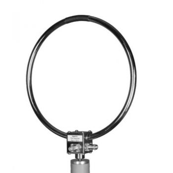
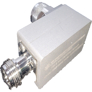
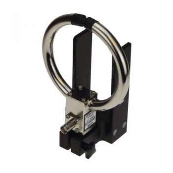
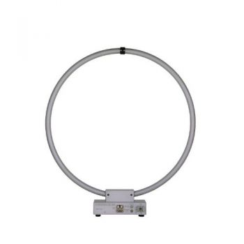
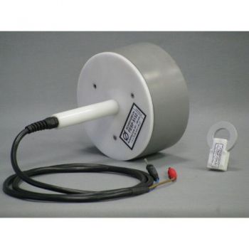
HFRA 5159- DC - 400 kHz Transmitting loop antenna
- The circular transmitting loop antenna
- DC - 400 kHz
- diam. 250 mm
- turns 28
- BNC Connectors

Data Sheet
SPECIFICATIONS
HFRA 5159 - Passive Magnetic Antennas, Tx-Loop AntennaThe transmit loop antenna HFRA 5159 was designed to generate well defined magnetic fields in the frequency range from DC to 400 kHz. With the slightly reduced performance the loop can be used in the frequency range up to 2 MHz. The loop, consisting of 28 turns, is shielded against E-fields. The nickel-plated brass housing contains resistors to verify the loop current by voltage measurement. The loop antenna has a flat frequency response over the entire frequency range. The loop can be mounted at its female large camera thread. The generated magnetic field is proportional to the loop current. A tabular indicates the field-strength values in A/m and dBμA/m to be expected with the loop current of 100 mA. Additionally, the relative decrease of magnetic field-strength referred to as the center of the loop antenna can be found. The lower magnetic field strength can be achieved by scaling the current to the respective value. With a feed current of 10 mA instead of 100 mA, the tabular values decrease by a factor of 10, which corresponds to a reduction by 20 dB in logarithmic measure. All specified magnetic field strength refers to the component which is perpendicular to the loop-plane. Application: The HFRA 5159 comes with 3 BNC connectors. Connector A is used to feed the loop with a 50 Ω source with constant voltage, which generates a constant magnetic field-strength versa frequency. Connector C is used to monitor the loop current by measuring the voltage drop across a 10 Ω resistor. This operation mode uses a linearisation of the loop current by a series resistor, which causes a flat frequency response, but the achievable field strength is limited. Alternatively, the loop antenna can be driven through Connector B, which presents the loop inductance in series with the 10 Ω resistor. In this case, the loop current has to be checked by measuring the voltage drop across the 10 Ω resistor. This operation mode allows us to generate higher field-strength levels but requires current monitoring and input voltage adjustment for each frequency. We recommend using voltage measuring equipment with high impedance to measure at connector C.
Specifications:
|
OTHER PRODUCTS IN THE SAME CATEGORY:
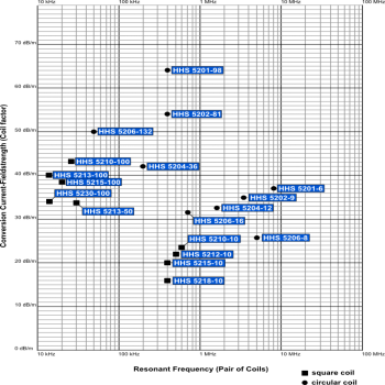
Helmholtz Coils Overview
Coil Set 4-39_9k-150k EN 61000-4-39 & RS101 9kHz - 150kHz, Tx & Rx Set
CAB1356m Coupling Network for 13.56 MHz
CAB134k Coupling Network for 134kHz
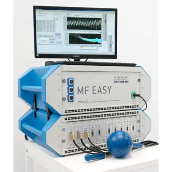
MF EASY, DC-400 kHz, MAGNETIC FIELD EXPOSURE ASSESSMENT SYSTEM
Coil Set 4-39_150k-26M EN 61000-4-39, 150 kHz - 26 MHz, Tx & Rx Set
HFRA 5164, 10 kHz - 120 MHz Transmitting loop antenna
FMZB 1519 C 9kHz-30MHz, Active Receiving Loop Antenna
FMZB 1519-60 D Active Receiving Loop Antenna
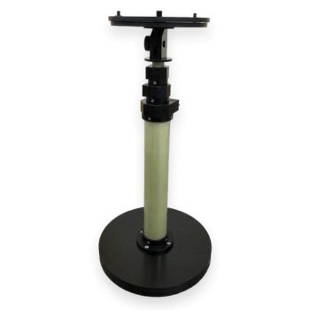
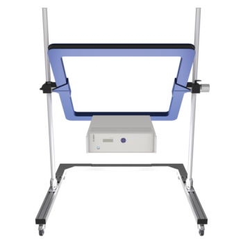
LAS-2000 Loop Antenna Stand
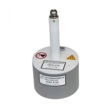
FESP 5139 - DISCONTINUED replaced by HFRA 5164
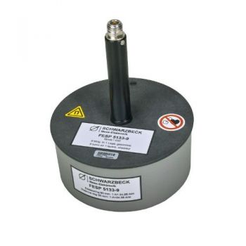
FESP 5133-9 - 10 kHz - 3 MHz Radiating Loop
FESP 5132 - DC - 150 kHz Radiating Loop
FESP 5133 - DC - 200 kHz Radiating Loop
FESP 5133-1330 - DC - 50 kHz Radiating Loop
FESP 5135 - DC - 300 kHz Radiating Loop
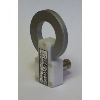
FESP 5134-40 - 5 -250 kHz Circular Screened Coil
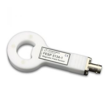
FESP 5134-1 - 10 - 400 MHz Circular Screened Coil
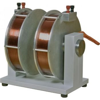
AGEM 5520 - Electromagnet with variable Air Gap

