
GTEMCELL GTEM 250 F – GTEM250 F SAE – GTEM FV
Meets IEC/EN 61000-4-20, SAE J1752/3, IEC 62132-2 and IEC 61967-2
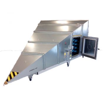
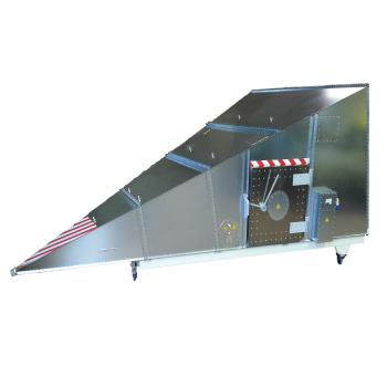
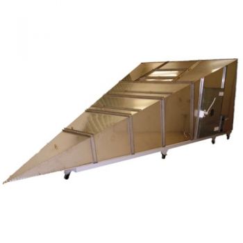
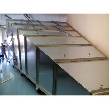
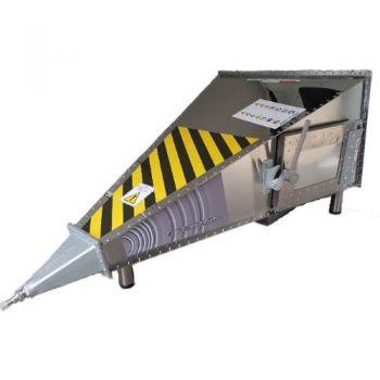
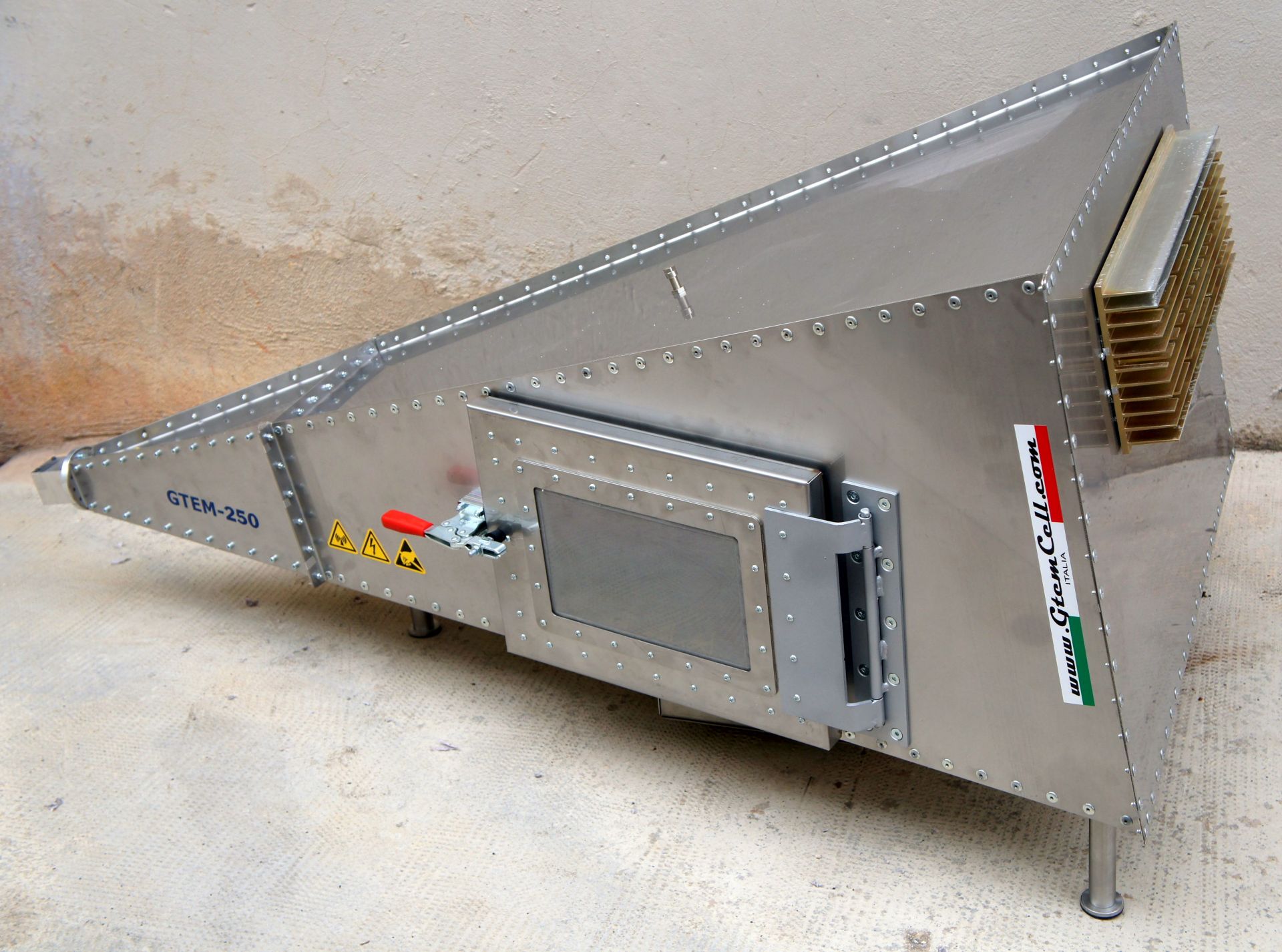
The GTEM cell is, in principle, a tapered coaxial line (offset septum plate), which is terminated by a hybrid combination of discrete resistors and RF absorbers to achieve a 50 Ohm broadband match. It is applied for Measuring of Emission, Radiated, radio frequency field-immunity test.
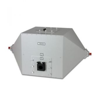
Model GTEMCELL GTEM250 F with Ferrite tiles on the bottom offers a wider operating bandwidth with peak smoothed and flat response starting from DC to microwave frequencies. It is an indispensable tool for researchers and developers engineers!
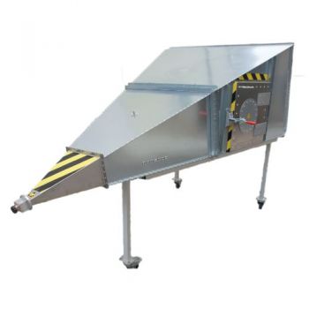
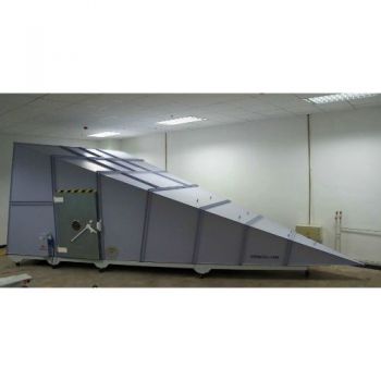
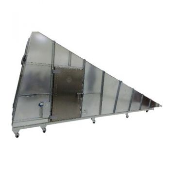
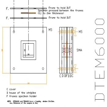
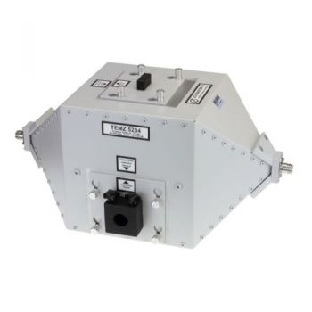
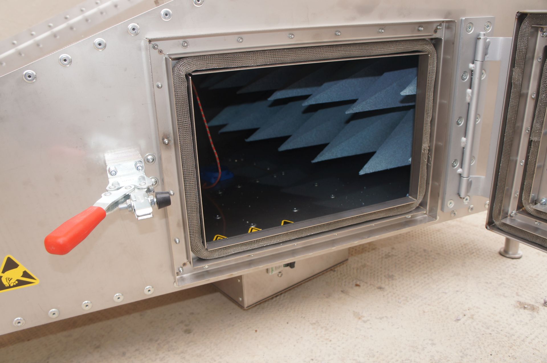
Model GTEMCELL GTEM250 F SAE includes a special opening to test integrated circuits, dimensions: 80 mm x 80 mm on Approx. 45 mm septum height, closed from a removable panel where are placed the IC under testing.
The standards SAE J1752/3 and IEC 61967-2 define a method for measuring the electromagnetic radiation from an integrated circuit (IC). The IC itself is mounted on a test board on a panel that is clamped in the upper face close to the top of the GTEM cell. The test board becomes a part of the cell wall.
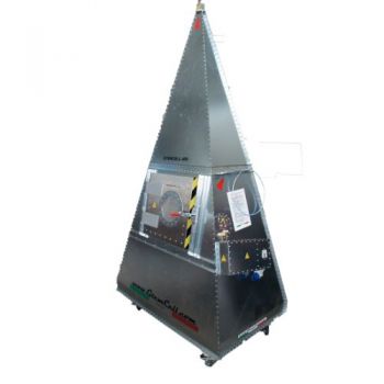
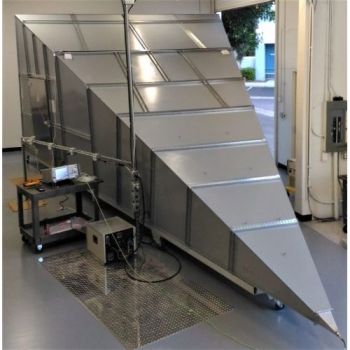
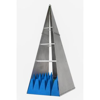
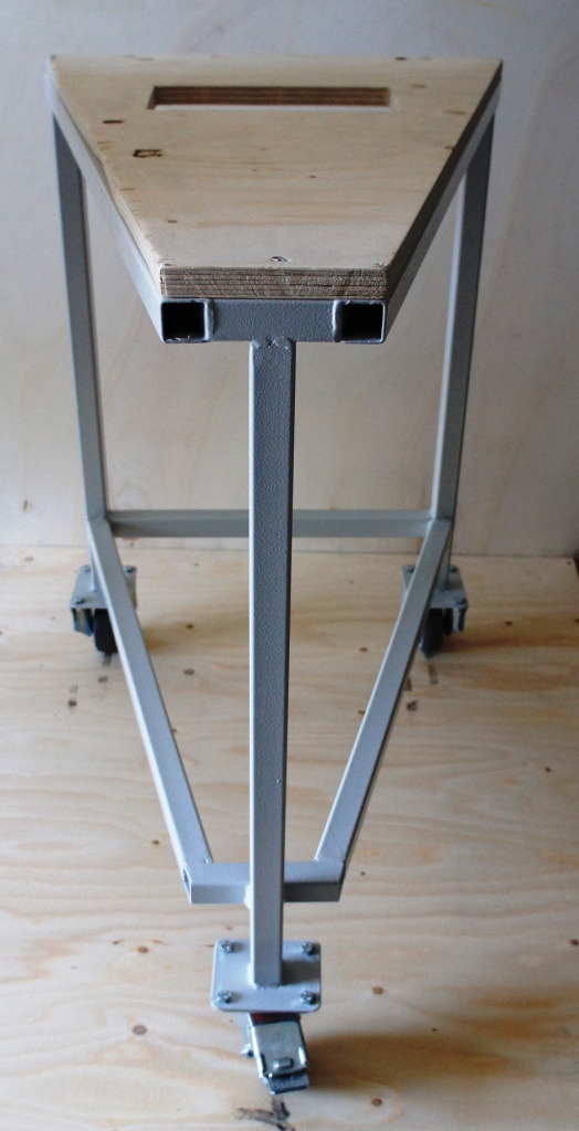
The GTEMCELL GTEM250 FV is a vertical stand-alone model developed to reduce at the minimum the occupied area in the test lab with the maximum EUT test volume
A receiver or spectrum analyzer measures the RF emissions emanating from the integrated circuit and impressed onto the septum of the cell. The standard IEC 62132-2 defines the immunity test set-up on integrated circuits tested with a GTEM.
| GTEM-250 F Datasheet Download GTEMCELL GTEM xxx SAE |
|
| GMain Technical Specifications / Max EUT Size | |
| Frequency range | DC – 20GHz* |
| Septum Height [mm]: | 250 |
| Max EUT Size (LxWxH)cm | 20x20x15 cm. |
| Defined test Vol. within 6dB | 8,3×8,3×8,3 cm. |
| Typical VSWR | 1:1,2 |
| Typical VSWR at the critical frequency | <1:1,6 |
| Max Input power, W continuous/*pulsed | 1000/*2,5Kw |
| Input connector | 7/16 or N |
| Nominal impedance | 50 |
| Window in the door | 24x14cm |
| Mechanical Dimensions | |
| Outer LxWxH [cm]: | 125x64x44 |
| Door WxH [cm]: | 30x20cm. |
| Weight Kg. Approx. | 40 |
| Electrical Specifications | |
| Mains connectors | Fix/CEE |
| Main Switch | 16A magneto-thermal |
| Input Socket plug | 16Aac (Single phase + ground) IEC |
| Output Socket EUT tape | 16Aac (Single phase + ground) Schuko |
| Additional EUT sockets | Optional |
| Ground connection | M6 bolt |
| Secondary DC filter wires | 10Amp. 250V AC/DC, 2 wires |
| Channel for fiber optic leads | 3 couples |
| RF feed-thru connector | N.1 N female type |
| RF feed-thru SMA type connectors | N.2 SMA female type |
| Electrical Equipment / Options |
|
| AC filter 30A/2 wire (2PH+Ground) | |
| AC filter 16A/4 wires (3PH+N+Ground) | |
| Electrical safety interlock | |
| Indoor lighting 10W | |
| 9-poles signal filter (DB9) | |
| 25-poles signal filter (DB25) | |
| Channel for fiber optic leads (3 couple) | |
| Additional RF feed-thru N-type connector | |
| Additional RF feed-thru SMA type connector | |
| RJ11 (RJ9) feed-thru connector | |
| RJ45 feed-thru connector | |
| Video camera system | |
| Technical panel pre-drilled for options | |
| Mechanical Equipment / Options | |
| Gas / Water feedthrough plates | |
| Honeycomb panel | |
| Fans N.1 12x12cm | |
| Empty Technical panel | |
| Wheeled undercarriage | |
  |
||