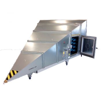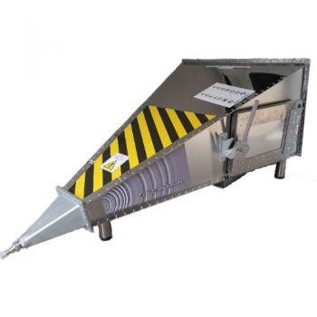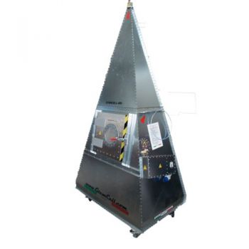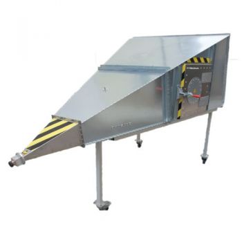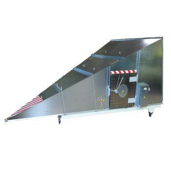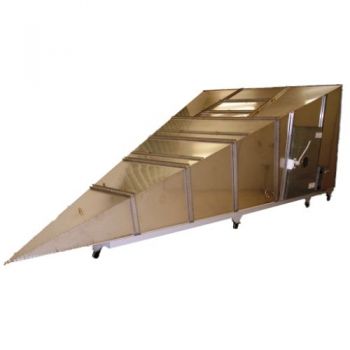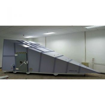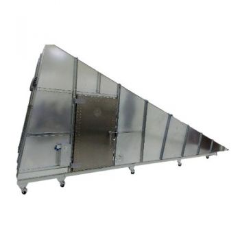
GTEM 2000 & GTEM 2100
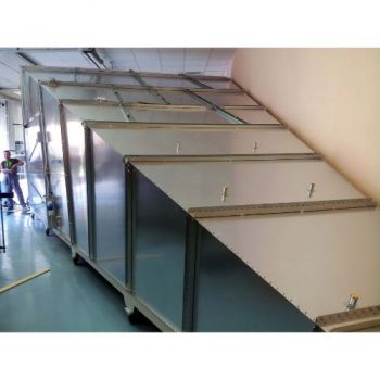
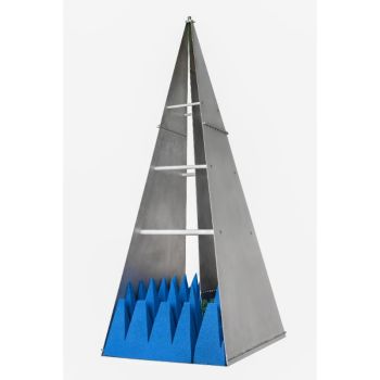
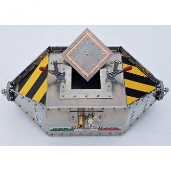
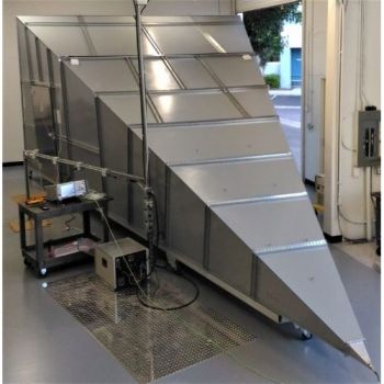
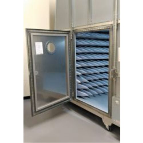
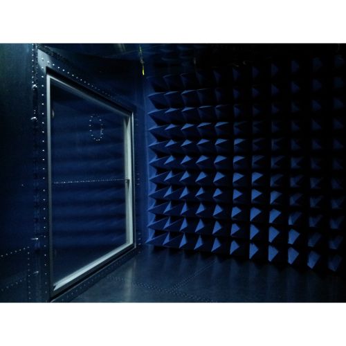
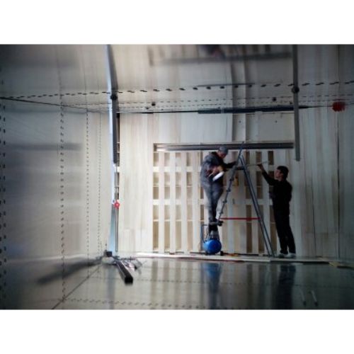
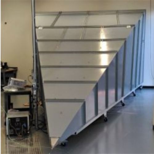
The GTEMCELL GTEM-2000 is a TEM waveguide with the upper-frequency limit extended to the GHz range. It is under consideration as an alternative measurement facility for both radiated emission and immunity measurements. It is included in the standard IEC 61000-4-20 “Emission and Immunity Testing in Transverse Electromagnetic (TEM) Waveguides”. Compared to other measuring methods like EMC test in anechoic chambers or OATS (Open Area Test Sites), GTEM-cells offer some significant advantages for the testing of small and medium-sized EUT´s (Equipment Under Test) up to a frequency range of 20 GHz. Quick turn arounds of the EUT, as well as, numerous testing variations are easy and fast to handle. Switching from emission to immunity testing requires only simple adjustments from receiver input to the amplifier output.
PARTNER:
MARKETS:
TEST STANDARDS:
|
GTEMCELL GTEM 2000 & GTEM 2100 |
|
|
The GTEMCELL GTEM-2000 & GTEM-2100 is a TEM waveguide with the upper-frequency limit extended to the GHz range. It is under consideration as an alternative measurement facility for both radiated emission and immunity measurements. It is included in the standard IEC 61000-4-20 “Emission and Immunity Testing in Transverse Electromagnetic (TEM) Waveguides”. Compared to other measuring methods like EMC test in anechoic chambers or OATS (Open Area Test Sites), GTEM-cells offer some significant advantages for the testing of small and medium-sized EUT´s (Equipment Under Test) up to the frequency range of 20 GHz. Quick turn arounds of the EUT, as well as, numerous testing variations are easy and fast to handle. Switching from emission to immunity testing requires only simple adjustments from receiver input to the amplifier output. You are irrespective of long waiting times associated with off-site test labs or weather and ambient delays that can occur at OATS facilities. Whether you are at the design qualification, pre-compliance, compliance, or production sampling stage, the GTEM is the right choice for you!
|
|
|
GTEM2000 – Main Technical Specifications / Max EUT Size |
|
|
Frequency range: |
0,01 MHz – 20GHz* |
|
Septum Height [mm]: |
2000 |
|
Max EUT Size (LxWxH)cm |
150x150x132 cm. |
|
Defined test Vol. within 6dB |
67x67x67 cm. |
|
Typical VSWR |
1:1,2 |
|
Typical VSWR at the critical frequency |
<1:1,6 |
|
Max Input power, W continuous/*pulsed |
1000/*2Kw |
|
Input connector |
N or 7/16″ |
|
Nominal impedance |
50 Ohm |
|
Window in the door |
Diam.200 mm. |
|
Empty Technical panel |
N.2 Diam.200 mm. |
|
|
|
|
Mechanical Dimensions |
|
|
Outer LxWxH [cm]: |
933×480,5×306 |
|
Door WxH [cm]: |
100×160 clear passage |
|
Weight Kg. Approx. |
2000 |
|
Wheeled undercarriage (Cost Option) |
25cm high |
|
|
|
|
Electrical Specifications |
|
|
Mains connectors |
Fix/CEE |
|
Main Switch |
16A magneto-thermal |
|
Input Socket plugs |
IEC 16A(Single phase+ground); 250V Banana plugs 10A 250V |
|
Output Socket EUT tapes |
Schuko 16A (Single phase+ground) 250V |
|
Banana plugs 10A 250V |
|
|
Ground connection |
M6 bolt |
|
AC filter wires (Single PH+Ground);AC/DC filter wires |
16Amp. 2 wires+ground; 10A, 2 wires |
|
Channel for fiber optic leads |
3 couples |
|
RF feed-thru connectors |
No.1 N-N, No.2 SMA-SMA double female |
|
Indoor LED light |
2x20W |
|
|
|
|
Electrical Equipment / Options |
|
|
AC filter 30A/2 wire (2PH+Ground) |
DC Filter feed-thru 300A 450V |
|
AC filter 16A/4 wires (3PH+N+Ground) |
|
|
Additional EUT sockets tapes |
|
|
Electrical safety interlock |
|
|
9-poles signal filter (DB9) |
|
|
25-poles signal filter (DB25) |
|
|
Channel for fiber optic leads (6 couples) |
|
|
Additional RF feed-thru N or SMA connectors |
|
|
Input RF connector 7/16″ |
|
|
RJ45 (RJ11) feed-thru connector |
|
|
Technical panel pre-drilled for options |
|
|
Video camera system |
|
|
|
|
|
Mechanical Equipment / Options |
|
|
Gas / Water feedthrough plates |
|
|
Honeycomb panel |
|
|
Larger Door upon request: 160x160cm |
|
|
Secondary doors: 40x40cm, 60x60cm or 80x80cm, |
|
|
|
|
|
|
|
|
GTEM Power vs. Field
|
GTEM´s Main differences from competitors:
|


