CAL CMAD 1614, Calibration fixture for CMAD 1614
- Calibration fixture for Common-Mode Absorbing Clamp
- (10) 30 - 200 (1000)MHz
PARTNER:
MARKETS:
CATEGORIES:
TEST STANDARDS:

Data Sheet
SPECIFICATIONS
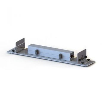
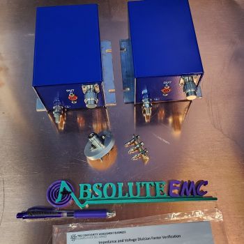
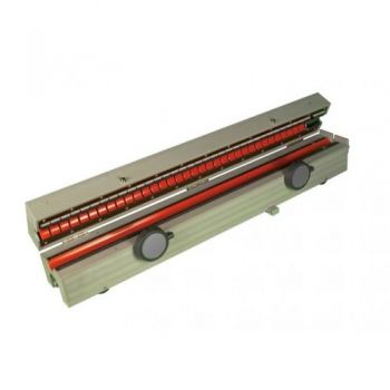
CAL CMAD 1614, Calibration fixture for CMAD 1614The CAL CMAD 1614 calibration fixture is used to calibrate/verify the performance of the common-mode absorption device CMAD 1614. The fixture consists of an aluminum base plate with two side plates, adjustable in height and position and each of them equipped with N-connector and inner conductor fixture. A variety of inner conductors with 4 mm diameter is part of the delivery. The calibration fixture was designed for measurements acc. to CISPR 16-1-4 sections 9.5 and 9.6.
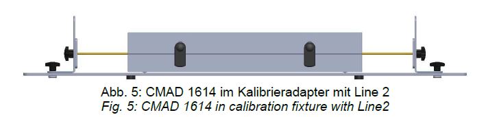
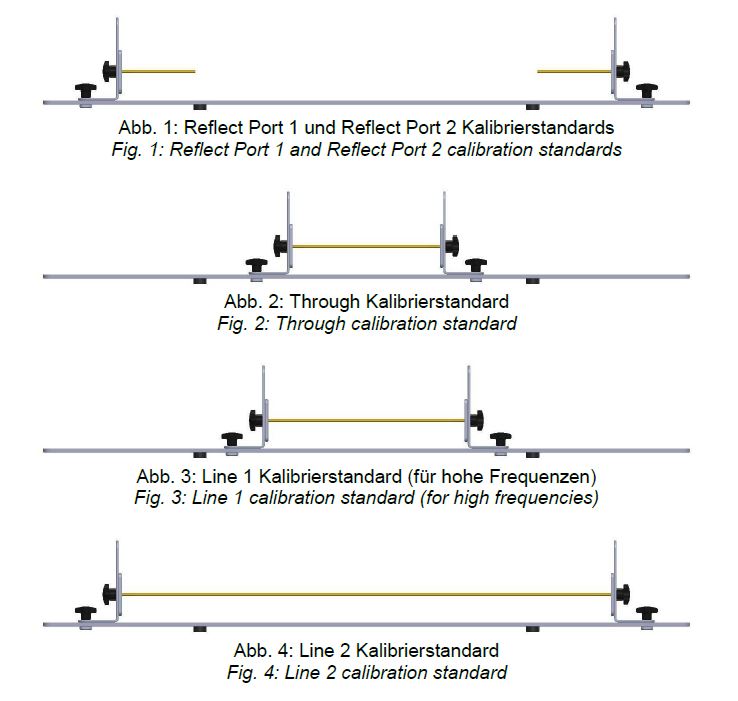
Application First of all it is recommended to adjust the height of the inner conductor that it is centered in the CMAD. This can be done by releasing both star knobs and moving the N-connector to the desired position. As soon as the correct height is found, tighten the star knobs and repeat the same for the opposite side. It is advisable to embed the CMAD in the calibration fixture and verify the correct height of the inner conductor, if needed, do a fine adjustment. The height shall not be changed during the TRLcalibration procedure and the following measurement to obtain meaningful results. Calibration The calibration of the CMAD 1614 can be done using the TRL-method. TRL means "Through", "Reflect", "Line" and is usually implemented in modern vector network analyzers. Further information about the application of the TRL-method can be found in the documentation of the network analyzer. The same applies for the data input of the calibration standards. The following table contains the data of the calibration standards to be used by the vector network analyzer. It is worth to notice that the actually measured length of the inner conductors deviates by 14 mm or 28 mm from the tabular values since the inner conductor plugs come with 14 mm length on each side.
|


OTHER PRODUCTS IN THE SAME CATEGORY:


AN-ABCD-60, 60 Amp Artificial Network, EV HV Testing
CABCISPR2532A, CISPR 25, 5uH, 32 A LISN
CABCISPR2515A, CISPR 25, 5uH, 15 A LISN
Cx 10000-xxx-xxx, 1000V, 100 - 600 amp 10mF HV Capacitor Cabinet
NSLK 8117, 9 kHz - 30 MHz, 250V / 10A, 50 µH, 2 Path LISN
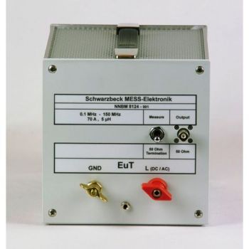
NNBM 8124, 10 kHz - 150(400) MHz, High Voltage, 70A, single path, 5µH LISN
MDS 21 C, 30 - 1000 MHz, EMI Absorbing Clamp
EMCL 6146, 10 - 1000 MHz, EM Coupling Clamp and CAL EMCL Cal Fixture
FTC 101 B Decoupling Clamp
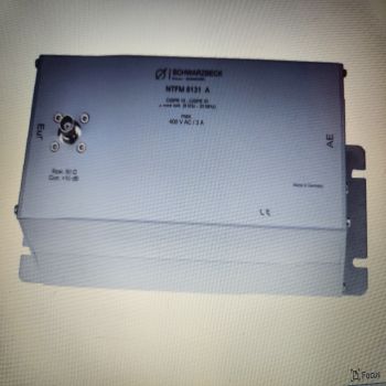
NTFM 8131 A, ISN for 2 unshielded Unsymetrical lines, Acc CISPR 32
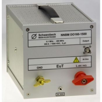
NNBM DO160-1500, 10 kHz - 400 MHz, 200A, 5µH LISN, DO-160
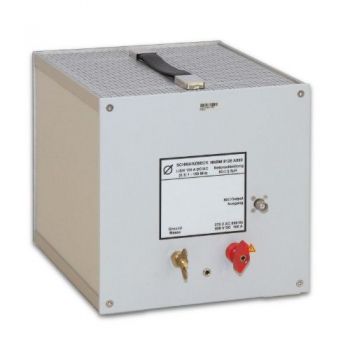
NNBM 8126 A890, 10 kHz - 400 MHz, 75A, 5µH LISN, DO-160
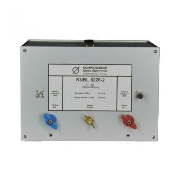
NNBL 8226-2, 9 kHz - 100 MHz, 70A, 50µH, Two Path LISN
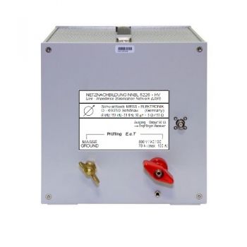
NNBL 8226-HV, 9 kHz - 100 MHz, 70A, 50µH, Single Path LISN
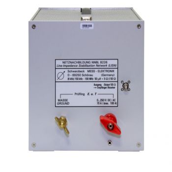
NNBL 8226, 9 kHz - 100 MHz, 70A, 50µH, Single Path LISN
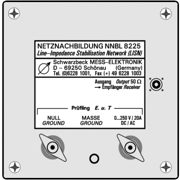
NNBL 8225, 9 kHz - 100 MHz, 20A, 50µH, Single Path LISN
NSLK 8126, 9 kHz - 30 MHz, 250V / 16A, 50 µH, 4 Path LISN
NSLK 8127, 9 kHz - 30 MHz, 250V / 16A, 50 µH, 2 Path LISN
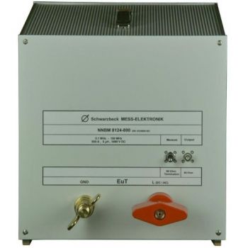
NNBM 8124-800, 0.1 - 150 MHz, High Voltage, 800A, single path, Automotive LISN

