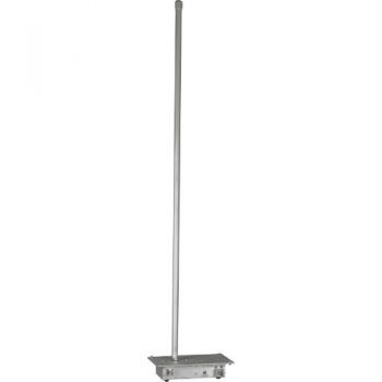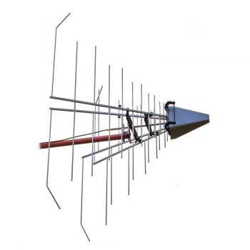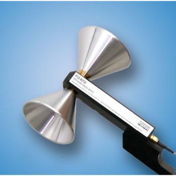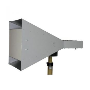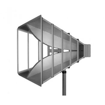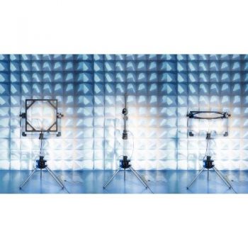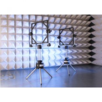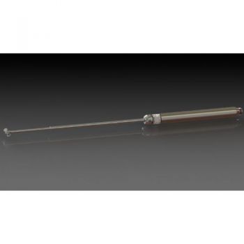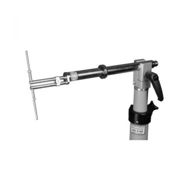
UHA 9125 C - 0.75 - 2 GHz, UHF Half-Wave Dipole
- Tuneable UHF - Half -Wave Dipole
- with EMI -Balun
- 0.75 - 2 GHz with 4 sets of elements
- LE = 180, 140, 100, 80 mm
UHA 9125 C - UHF Half-Wave DipoleRadiation in front direction under free-space far-field conditions. Gain at 900 MHz / 1 GHz near 0 dBd @ 2.15 dBi (= lossless ideal half-wave dipole). To measure Field-Strength add ANTENNA FACTOR and Cable Loss in dB to Test Receiver reading in dBμV across 50-ohm input. The result is Field-Strength in dBμV/m To generate an EFFECTIVE RADIATED POWER (referenced to the ideal lossless half-wave dipole) feed the power - identical to the required ERP - into the N connector of this antenna. Use a 50-ohm coaxial cable and measure power at the N plug of the table next to the female N socket at the UHA 9125-C, tuned to 900 MHz / 1 GHz (or any other frequency, considering the difference to 0 dBd / 2.15 dBi). Increase the generator power by the amount of cable loss.
Specifications:
Insertion of an attenuator is advisable if the equipment presents a high internal SWR (e.g. in the 0 dB position of an internal step attenuator. In this case the attenuation must be added to the antenna factor (dB/m) or subtracted from the gain (dBi, dBd).
|


