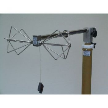
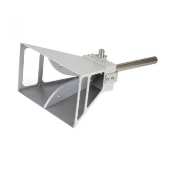
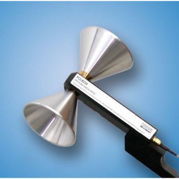
UBA 9116, 160 to 1100 MHz, Biconical UHF broadband antenna
- Biconical UHF broadband antenna
- (160) 300 -1000 (1100) MHz
- 5 Watts

Data Sheet
Radiation Patterns
SPECIFICATIONS
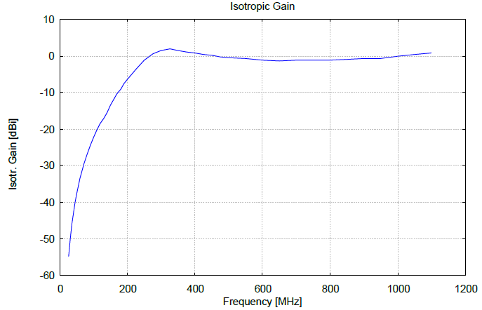
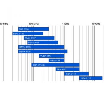
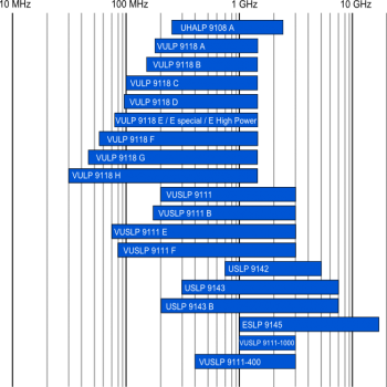
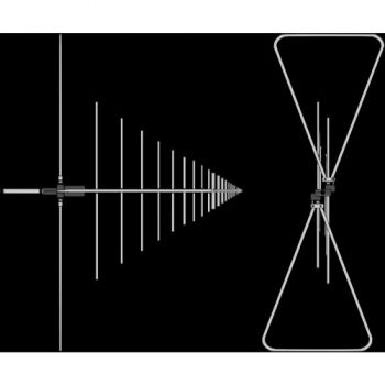
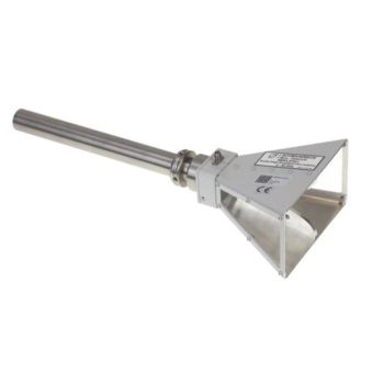
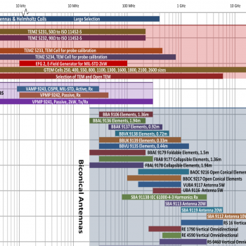
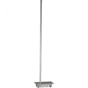
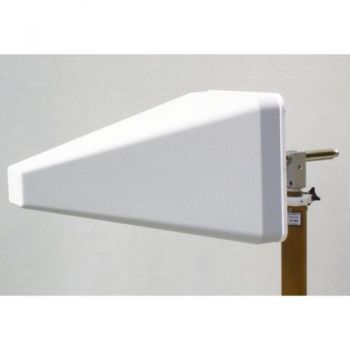
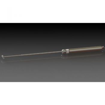
UBA 9116 UHF Biconical AntennaBoth for the measurement of Field Strengths and for the generation of defined Electromagnetic Fields (EMC) in the UHF range 300 MHz to 1 GHz a number of different antenna systems may be useful: Tuneable Half-Wave Dipoles (UHA 9105), Precision Dipoles UHAP, Log. -Periodic Antennas (UHALP 9108 A, VULP 9118 and more), Horn Antennas (BBHA 9120), and Standard Gain Antennas, and shown here, BICONICALS. Gain Antennas reduce errors by unwanted reflections, but their disadvantage in most cases is the frequency-dependent phase center, due to a non-circular H-pattern the ray to the ground reflection point may be of reduced intensity compared to the direct ray. Half-Wave Dipoles are often used as reference antennas. Their disadvantage with economical testing is the need for element adjustment with every frequency change (no automatic testing). In the VHF range the Biconical Broadband Antennas (BBA 9106 in holder/balun VHA 9103 or VHBA 9123) are in wide-spread use worldwide, they can be found on almost every antenna testing range or EMI/EMC Test Houses. With gain and antenna factor in the main frequency range (300-1000 MHz), they have similar gain and antenna factor figures as half-wave dipoles but do not require any adjustment. They possess a circular H pattern and a fixed phase center, important for short test sites. The Biconical UHF Broadband Antenna UBA 9116 shown here offers these attractive features in the UHF range (300 MHz - 1 GHz). With higher antenna factors (negative gain dBi) they may be used down to 160 MHz and up to 1.3 GHz. As this antenna radiates or receives perpendicular to the dipole plane in all directions, economical testing set-ups with two or more simultaneous functions are possible.
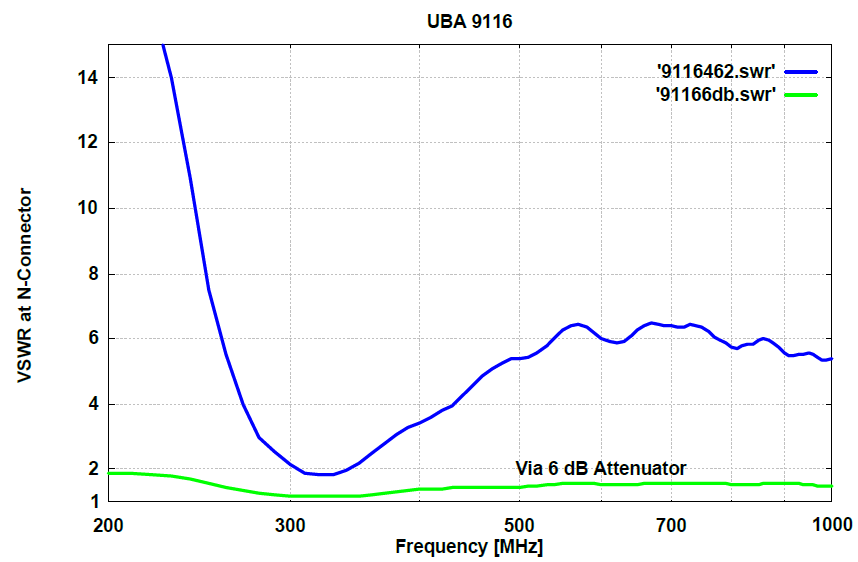
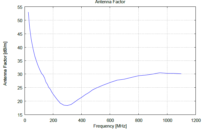
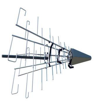
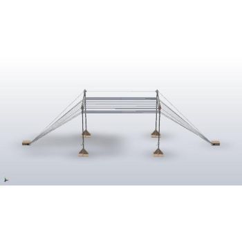
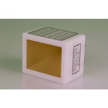
Application as an E Field Sensor For the measurement of E field-strength in the volt-per-meter region diode or FET sensors with short dipoles are frequently used. They offer wide bandwidths and reasonable flatness, but the accuracy for a defined frequency is limited. Calibration is usually performed in TEM cells. Their vertical width should be 5 times the length of the test dipole to obtain sufficient accuracy. In the case of a Crawford triplate cell the total height would be ten times the dipole length. Such large TEM cells suffer from a frequency limit in the VHF range. For EMC applications a calibration up to 1 GHz should be possible. The passive biconical Test Antenna UBA 9116 has primarily been designed for field-strength measurements in the range 300 MHz to 1 GHz, but may be used with dipole-like antenna factors between 200 MHz and 1.3 GHz. Such passive antennas with identical gain data can be accurately calibrated under free-space conditions with the "Two-Antenna-Method" that does not require a gain standard. The measurement uncertainty can be reduced to less than 1 dB under near-perfect free space conditions using a method developed here with simultaneous height-variation and averaging the results. The aim of designing E field sensors might be a very short dipole length to measure the field strength on a defined "spot". In case of immunity testing of practical equipment, e.g. of 19" boxes, the surface or volume of the EuT must be tested. In the case of varying field-strengths, a final definition must be established. An alternative method could be the use of an E field sensor of a comparable size compared to the EuT. With a total length of the biconical antenna of 325 mm, this condition is met for a number of applications. One of these applications is the field-strength measurement at a separation of 3m in front of the tip of a logarithmic-periodic antenna for immunity testing such as IEC 801-3, IEC 1000-4-3, ENV 50140, VDE 0847, part 3, also EN 50147. The calibration of the model UBA 9116 has been extended down to the low limit of the vhf band (25 MHz). The antenna factor with a minimum at 300 MHz rises again with lower frequencies. As the application is with high field strengths and sensitive test receivers are available for EMI testing, low f.s. levels down to 1 mV/m at 25 MHz can be measured. In these applications, a perfect shielding should be provided for coaxial cables and the test receiver because any signal interception would add to the (relatively low) voltage from the test antenna. As the VSWR of the antenna will be high at such low frequencies (far off-resonance), the test receiver input impedance should be 50 W resistive. This situation may be improved with VHF fixed attenuators of 6 dB or 10 dB between antenna output and coaxial cable.
|

OTHER PRODUCTS IN THE SAME CATEGORY:
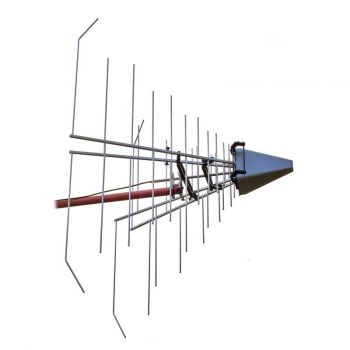
Log Periodic Antenna Overview
BBHA 9120 D - 1-18 GHz Double Ridged Horn Antenna
VULB 9162 - 30MHz - 7GHz TRILOG Broadband Antenna
BBHA 9120 L - 3-40 GHz Double Ridged Horn Antenna
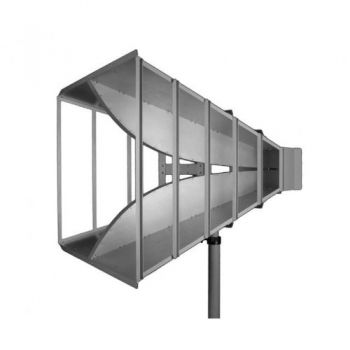
STLP 9129 Sp - 70 MHz - 10 GHz Stacked Log. Periodic Antenna
Antennas Overview Quick Find
VAMP 9243, 9 kHz - 30 MHz, Vertical Active Rod Antenna
STLP 9129 - 70 MHz - 10 GHz Stacked Log. Periodic Antenna
PCD 8250 Precision Conical Dipole 80 MHz – 3 GHz
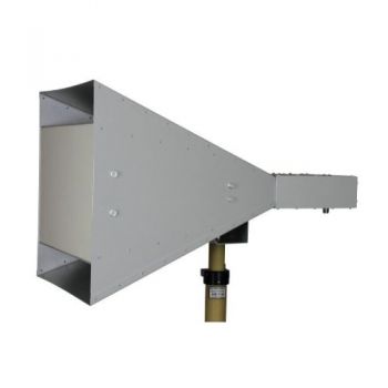
BBHA 9120 J - 0.8-6.2 GHz Double Ridged Horn Antenna
BBHA 9120 F - 0.2-2 GHz Double Ridged Horn Antenna
GENE-H-30-3K E/H 10kHz to 30MHz Field Generator / Stripline
BBHA 9170 - 15-40 GHz Horn Antenna
STLP 9149 - 0.7 - 9 GHz Stacked Log. Periodic Antenna
SBA 9112, 1 to 18 GHz, Small Biconical Microwave Antenna
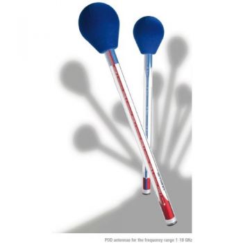
POD 16 & POD 618 Precision Omnidirectional Dipoles 1 - 18 GHz
PLA-R Receive, Precision Loop Antenna 9 kHz - 30 MHz
PLA-SET for Site Validation, Precision Loop Antenna 9 kHz - 30 MHz
SR50 - SR90 ISO 11452-5 Striplines

