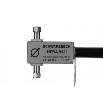
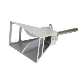
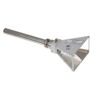
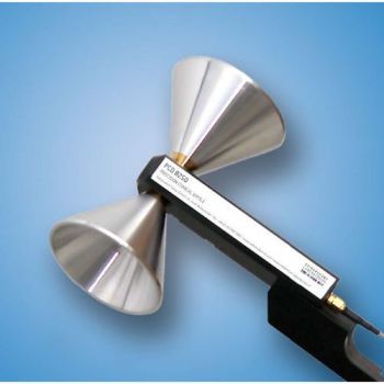
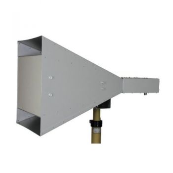
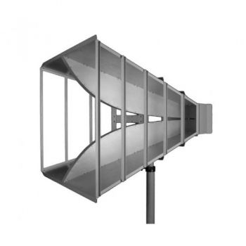
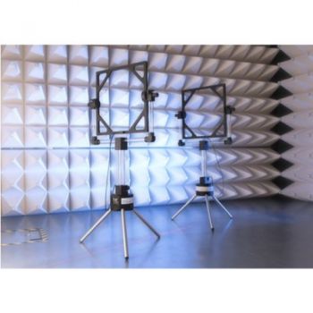
HFBA 9122 + Elements, 0.1 - 500 MHz, 10 W, Rx Biconical Antenna
- HFBA 9122 antenna holder/balun in combination with required elements:
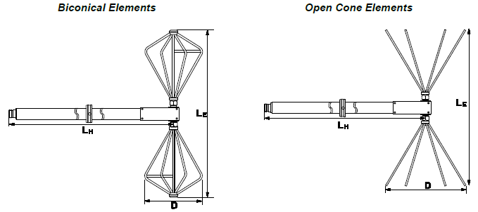
- Biconical Elements: BBA 9106, BBLA 9136, BBAK 9137, BBVK 9138
- Open-Cone Elements: FBAB 9177, FBAL 9178
- Especially to measure very high field strength
- 1:1 Balun
- 0.1-500 MHz(dependent on elements), 10 W, Type N (f)

Data Sheet HFBA 9122 w/BBVU 9135 & BBUK 9136
Data Sheet HFBA 9122 w/BBA 9106
Data Sheet HFBA 9122 w/BBAL 9136
Data Sheet HFBA 9122 w/BBAK 9137
Data Sheet HFBA 9122 w/BBVK 9138
SPECIFICATIONS
HFBA 9122 + Elements, 0.1 - 500 MHz, 10 W, Rx Biconical Antenna
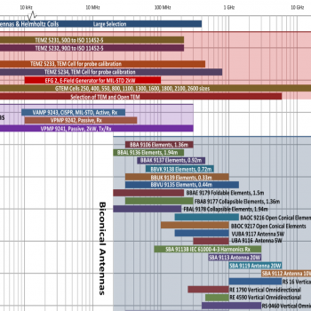
The 1:1 Balun/Holder HFBA 9122 was originally designed as a passive field probe to measure very high field strength at low frequencies from 100 kHz up. Depending on the element type in use the HFBA 9122 can be used up to 500 MHz. The characteristics of HFBA 9122 in the VHF range are comparable to common biconical antennas. The HFBA 9122 balun accepts several biconical element sizes, e.g. BBVU 9135 or BBUK 9139, which allows an antenna factor shift to the desired application. In general, the antenna factor rises (reduction of sensitivity) with smaller elements. Application: The HFBA 9122 can be assumed as an electrically short antenna (Hertzian Dipole with LE << l). The Antenna Factor decreases by 20 dB / decade of frequency below 100 MHz. The result is a 20 dB / a decade of frequency decreasing field strength measuring range as indicated in the diagram (a constant noise floor or a constant voltage reading was assumed). For measurements of high field strength, the following difficulties may arise: A measurement error might be induced by insufficient shielding effectiveness of coaxial cables and measuring receiver. The HFBA 9122 offers by far more than 120 dB shielding effectiveness a value which is at least one order higher than the respective value of cables or receivers. Braid currents may affect the measurement results, therefore the used cables should be as short as possible. The presence of interfering braid currents can be checked by rotating the polarisation for 180 °. In cases where critical braid currents exist, the measured field strength differs by far more than 1 dB. A further method to determine the validity of the measured results is to remove the biconical elements and watch the reading (do not touch the element fixtures). If there is a considerable reading without elements, the reason might be either insufficient shielding effectiveness or braid currents. Braid currents can be suppressed by using ferrite loaded cables. Typical commercially available ferrite loaded cables are nearly useless in the frequency range of interest (< 30 MHz) because of their insufficient outer conductor inductance. A workaround can be achieved by the following technique: A thin double braid coaxial cable is wound 4 to 6 times through a ferrite core of very high permeability. The spacing between the ferrite cores on the cable should be 0.5 m each. In order to improve impedance matching the use of a fixed attenuator (e.g. 6 dB) is recommended since the short antenna elements have only capacitive characteristics and do not provide impedance matching therefore
|
OTHER PRODUCTS IN THE SAME CATEGORY:
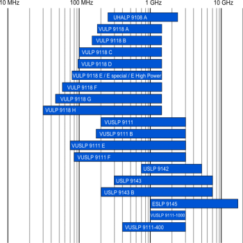
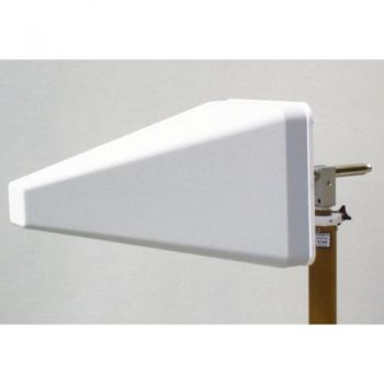
Log Periodic Antenna Overview
BBHA 9120 D - 1-18 GHz Double Ridged Horn Antenna
VULB 9162 - 30MHz - 7GHz TRILOG Broadband Antenna
BBHA 9120 L - 3-40 GHz Double Ridged Horn Antenna
STLP 9129 Sp - 70 MHz - 10 GHz Stacked Log. Periodic Antenna
Antennas Overview Quick Find
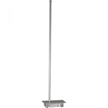
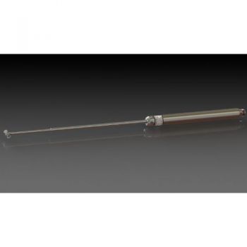
VAMP 9243, 9 kHz - 30 MHz, Vertical Active Rod Antenna
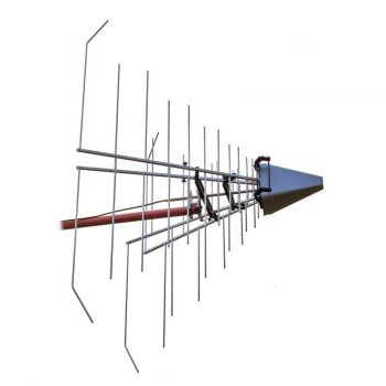
STLP 9129 - 70 MHz - 10 GHz Stacked Log. Periodic Antenna
PCD 8250 Precision Conical Dipole 80 MHz – 3 GHz
BBHA 9120 J - 0.8-6.2 GHz Double Ridged Horn Antenna
BBHA 9120 F - 0.2-2 GHz Double Ridged Horn Antenna
GENE-H-30-3K E/H 10kHz to 30MHz Field Generator / Stripline
BBHA 9170 - 15-40 GHz Horn Antenna
STLP 9149 - 0.7 - 9 GHz Stacked Log. Periodic Antenna
SBA 9112, 1 to 18 GHz, Small Biconical Microwave Antenna
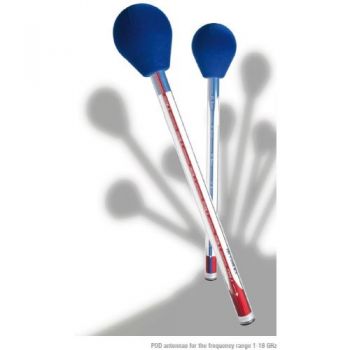
POD 16 & POD 618 Precision Omnidirectional Dipoles 1 - 18 GHz
PLA-R Receive, Precision Loop Antenna 9 kHz - 30 MHz
PLA-SET for Site Validation, Precision Loop Antenna 9 kHz - 30 MHz
SR50 - SR90 ISO 11452-5 Striplines

