BCOI 9180, Booster Coils for High Power Baluns
- Booster coils for varying the element loading of high power biconical
- Allows for better matching in low-frequency testing
- Helps compensate for chamber loading

Data Sheet
SPECIFICATIONS
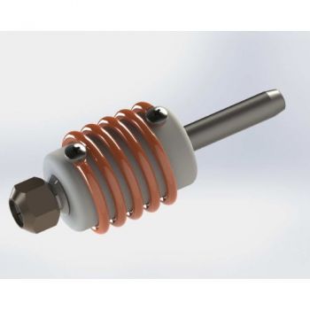
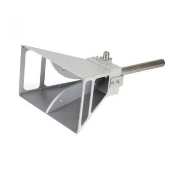
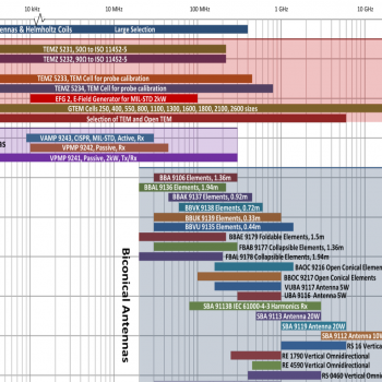
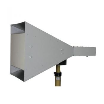
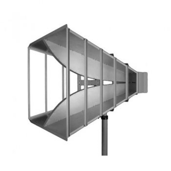
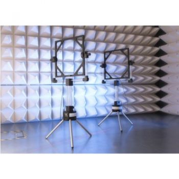
BCOI 9180, Booster Coils for High Power BalunsThe booster coils are used to generate highest field strengths in conjunction with a high power balun (e.g. VHBD 9134-4 or VHBD 9134) and radiating elements (e.g. BBAL 9136 or BBAE 9179) in the frequency range from 20 MHz to approx. 60 MHz. This frequency range has usually very high demands for amplifier power, since the antennas are small compared to the wavelength, their efficiency is low and the impedance matching is poor, which degrades the total efficiency of the immunity test system. A possible solution is the use of booster coils, which are placed between the balun's symmetrical terminals and the radiating elements. This increases the overall dimensions of the radiating elements by 14 cm only, but the electrical size increases significantly, which results in a better impedance matching and a remarkable increase of achievable field strengths. Although there are significant improvements in the low-frequency range obtained by the booster coils, it is not recommended to use them at higher frequencies. Depending on the antenna element in use, the maximum useful frequency of the booster coils is between 45 to 60 MHz.
Application: The booster coils are plugged into the element fixture clamps of the balun and tightened using the wrench delivered with the balun. Depending on the radiating element in use the balun can be equipped with an additional fixation bar, which prevents large elements from unwanted rotation. When using the radiating elements BBA 9106, BBAL 9136 or BBFA 9146, there is no need for a fixation bar. The bolt of the radiating element is placed inside the clamp fixture and the nut is tightened. The procedure for the opposite side is the same. Since the coil body is made of PTFE, the booster coils exhibit a material-specific long term deformation characteristic, which is called creeping or cold flow. Therefore light deformation can appear if the coils are under long term bending stress (e.g. at horizontal polarisation). We recommend removing the radiating elements immediately after the testing is finished. If testing takes several days, the rotation of the elements around 180 degrees should be made once each day. High temperatures may have an influence on the creeping process. Long term storage of the antenna with mounted elements in horizontal polarisation should be avoided in any case. Common size is 3 turn and 5 turn
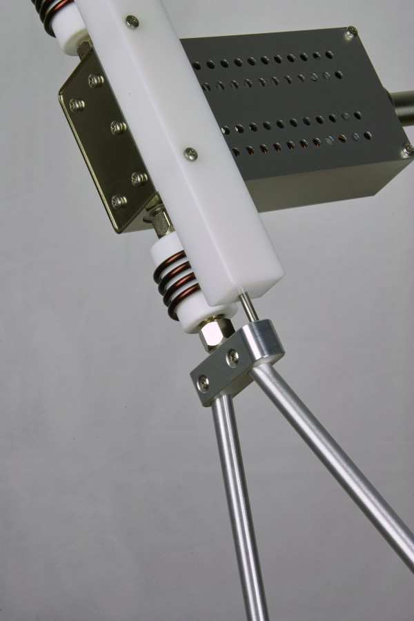
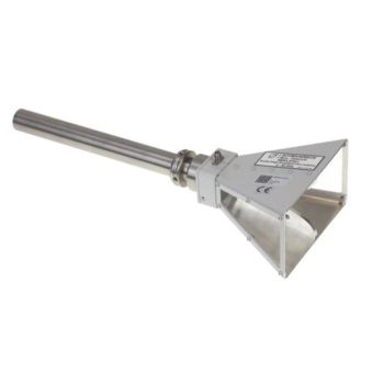
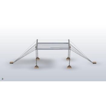
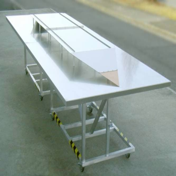
BCOI 9180, BOOSTER COILS FOR HIGH POWER BALUNS, installed with Long Holder
|

OTHER PRODUCTS IN THE SAME CATEGORY:
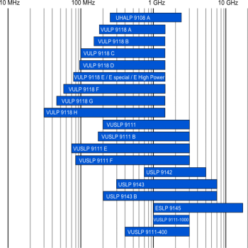
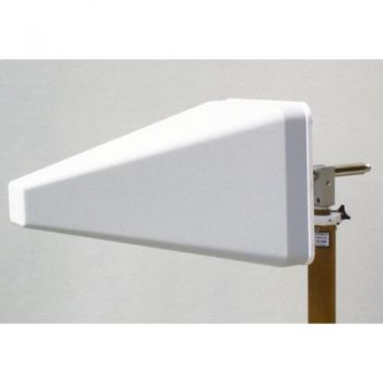
Log Periodic Antenna Overview
BBHA 9120 D - 1-18 GHz Double Ridged Horn Antenna
VULB 9162 - 30MHz - 7GHz TRILOG Broadband Antenna
BBHA 9120 L - 3-40 GHz Double Ridged Horn Antenna
STLP 9129 Sp - 70 MHz - 10 GHz Stacked Log. Periodic Antenna
Antennas Overview Quick Find
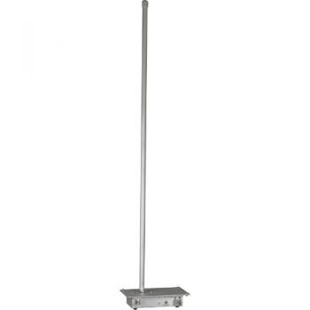
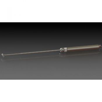
VAMP 9243, 9 kHz - 30 MHz, Vertical Active Rod Antenna
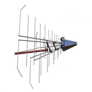
STLP 9129 - 70 MHz - 10 GHz Stacked Log. Periodic Antenna
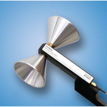
PCD 8250 Precision Conical Dipole 80 MHz – 3 GHz
BBHA 9120 J - 0.8-6.2 GHz Double Ridged Horn Antenna
BBHA 9120 F - 0.2-2 GHz Double Ridged Horn Antenna
GENE-H-30-3K E/H 10kHz to 30MHz Field Generator / Stripline
BBHA 9170 - 15-40 GHz Horn Antenna
STLP 9149 - 0.7 - 9 GHz Stacked Log. Periodic Antenna
SBA 9112, 1 to 18 GHz, Small Biconical Microwave Antenna
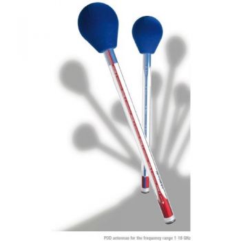
POD 16 & POD 618 Precision Omnidirectional Dipoles 1 - 18 GHz
PLA-R Receive, Precision Loop Antenna 9 kHz - 30 MHz
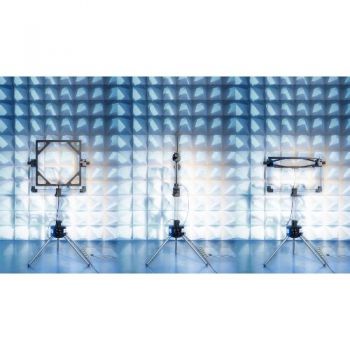
PLA-SET for Site Validation, Precision Loop Antenna 9 kHz - 30 MHz
SR50 - SR90 ISO 11452-5 Striplines

